


Dynamic Dosing Restrictor Selection Graphs
3A0869J 65
Dynamic Dosing Restrictor Selection Graphs
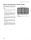
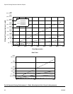
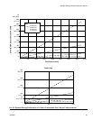
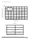
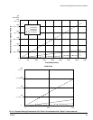
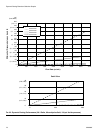
Use the graphs on pages 66- 70 as a guide to determine
the correct restrictor size for your desired flow and mate-
rial viscosity. Table 6 lists the available restrictor sizes.
Example:
Application: air spray system with a 5:1 mix ratio
Fluid Supply: 1:1 pumps at 100 psi (7 bar, 0.7 MPa)
Flow Rate: 300 cc/min at the gun
Select the Restrictor Size: choose either the 0.040
or 0.070 orifice, to ensure that the pressure differen-
tial is not more than 10-20 psi (0.7-1.4 bar,
0.07-0.14 MPa), provided the fluid viscosities are
similar to those tested.
• If the viscosity of component B is lower than the vis-
cosity of the chart used for selection you may need
to use a smaller restrictor or decrease the pressure
differential.
• If the viscosity of component B is higher than the
viscosity of the chart used for selection you may
need to use a larger restrictor or increase the pres-
sure differential.
• In systems using an air-assisted gun, if the fluid
pressure of component A is higher than the compo-
nent A pressure from the charts you may need to
use a larger restrictor or increase the pressure dif-
ferential.
* These restrictors are included in Injection Kit
15U955.
These restrictors are optional sizes, not included in
the Injection Kit.
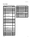
Table 6: Restrictor Sizes
Size Code Orifice Size Part No.
2* 0.020 15U936
3* 0.030 15U937
4* 0.040 15U938
5 0.050 15U939
6 0.060 15U940
7* 0.070 15U941
8 0.080 16D554