


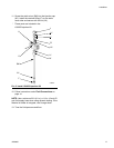
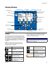
Display Module
3A0869J 25
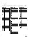
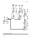
Screen Summary
NOTE: This summary is a one-page guide to the ProMix 2KE screens, followed by screen maps. For operating
instructions, see Basic Operation, page 31. For further detail on individual screens, see Run Mode Details, page
42, or Setup Mode Details, page 45.
Run Mode
The run mode has two screen sections that control the
mixing operations.
Mix (Screens 2-4, 38)
• Spray (Screen 2) controls most mixing opera-
tions.
• Batch (Screen 3) controls dispense of a set vol-
ume.
• Totals (Screen 4) displays grand and batch
totals for materials A1 (A2, A3) and B.
• Job Number (Screen 38) displays job number
and user number
Error Log (Screens 5-14)
• 10 screens, 5 errors per page
• Displays date, time, and error
Setup Mode
The setup mode has four screen sections that allow an
authorized user to choose the exact settings needed for
the system:
Configure (Screens 18-21)
• Configure 1 (Screen 18) controls system type
(pump or meter), dosing type (sequential or
dynamic dosing), gun flush box enable, number
of guns (1 or 2), and system color configuration
(1 or 3).
• Configure 2 (Screen 19) controls hose length
and diameter for one or two guns and flow rate
region for dynamic dosing.
• Configure 3 (Screen 20) controls language (for
optional USB Module), date format, date, time,
password setting, and backlight timer.
• Configure 4 (Screen 21) controls units for dis-
tance and volume.
Recipe (Screens 27-33)
• Recipe 0 (Screen 27) includes timers for the
system first, second, and third flush and a third
flush material selection.
• Recipe 1-1 (Screen 28) and 1-2 (Screen 29)
control Material 1/Color 1 parameters and flush.
• Recipe 2-1 (Screen 30) and 2-2 (Screen 31)
control Material 2/Color 2 parameters and flush.
• Recipe 3-1 (Screen 32) and 3-2 (Screen 33)
control Material 3/Color 3 parameters and flush.
Maintenance (Screens 24-26)
• Maintenance 1 (Screen 24) controls mainte-
nance timer actual and target for Meter A, Meter
B, Solvent Valve A, and Solvent Valve B.
• Maintenance 2 (Screen 25) controls dose
valves A1 and B maintenance timer actual and
target. Dose valves A2 and A3 are included if 3
colors are selected on Configure 1 (Screen 18).
• Maintenance 3 (Screen 26) controls fluid and air
filter maintenance timers, actual and target.
Calibration (Screens 22 and 23)
1-Color
• Calibration 1 (Screen 22) controls k factors
(cc/pulse) for Meter A and Meter B.
• Calibration 2 (Screen 23) allows the user to per-
form a calibration.
3-Color
• Calibration 1 (Screen 22) controls k factors
(cc/pulse) for Meter B and for Meter A using col-
ors A1, A2, and A3.
• Calibration 2 (Screen 23) allows the user to per-
form a calibration.
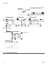
Troubleshooting Mode
The troubleshooting mode has three screen sections
that allow an authorized user to troubleshoot system
operation. See F
IG. 17, page 30.
System Inputs (Screen 35)
Membrane Test (Screen 36)
System Outputs and Manual Activation (Screen 37)