


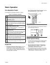

Basic Operation
3A0869J 31
Basic Operation
Pre-Operation Tasks
Go through the Pre-Operation Checklist in Table 2.
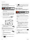
Power On
1. IS Systems (Alternator Power Supply): Set pump
air regulators to minimum setting. Open main air
valve to start air-powered alternator. Main air pres-
sure is displayed on gauge. Display Module screen
will display after five seconds.
Non-IS Systems (Wall Power Supplied): Turn the
AC Power Switch ON (I = ON, 0 = OFF).
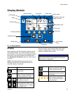
2. Graco logo will display after five seconds, followed
by Run Mix Spray (Screen 2).
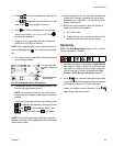
Initial System Setup
1. Change optional setup selections to desired param-
eters, as described in Configure 1-4 (Screens
18-21), page 46.
2. Set recipe and flush information as described in
Recipe 0 (Screen 27), Recipe 1-1 (Screen 28),
and Recipe 1-2 (Screen 29), page 47.
3. Set maintenance timers for meters, solvent valves,
dose valves, fluid filters and air filters, as described
in Maintenance 1-3 (Screens 24-26), page 48.
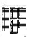
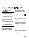
Table 2: Pre-Operation Checklist
Checklist
System grounded
Verify all grounding connections were made. See
Grounding, page 21.
All connections tight and correct
Verify all electrical, fluid, air, and system connec-
tions are tight and installed according to the man-
ual instructions.
Fluid supply containers filled
Check all supply containers - A1 (A2 and A3, if
present), B, and solvent.
Dose valves set
Check that the dose valves are set correctly. Start
with the settings recommended in Valve Set-
tings, page 38, then adjust as needed.
Fluid supply valves open and pressure set
Component A and B fluid supply pressures should
be equal unless one component is more viscous
and requires a higher pressure setting.
Solenoid pressure set
75-100 psi inlet air supply (0.5-0.7 MPa, 5.2-7
bar)
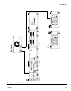
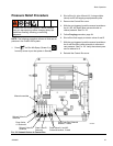
FIG. 18. Power Switch
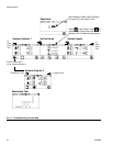
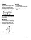
FIG. 19. Run Mix Spray (Screen 2)
I = ON
ti16336a