


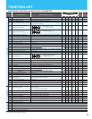

= Allowed
= Not permitted
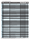
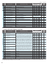
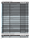
Code Function Name Monitored data or setting
Default Setting
Setting
during
operation
(allowed or not)
Change
during
operation
(allowed or not)
SJ700/SJ700D(CTmode)
SJ700B
-FE -FU -F -F -FU
Free setting of V/f
characteristic
b108
Free-setting V/f frequency (5)
0. to "free-setting V/f frequency (6)" (Hz)
0. 0. 0. 0. 0.
b109
Free-setting V/f voltage (5)
0.0 to 800.0 (V)
0.0 0.0 0.0 0.0 0.0
b110
Free-setting V/f frequency (6)
0. to "free-setting V/f frequency (7)" (Hz)
0. 0. 0. 0. 0.
b111
Free-setting V/f voltage (6)
0.0 to 800.0 (V)
0.0 0.0 0.0 0.0 0.0
b11
Free-setting V/f frequency (7)
0.0 to 400.0 (Hz) (*4)
0. 0. 0. 0. 0.
b11
Free-setting V/f voltage (7)
0.0 to 800.0 (V)
0.0 0.0 0.0 0.0 0.0
Others
b120
Brake control enable (*3)
00 (disabling), 01 (enabling)
00 00 00 00 00
b121
Brake wait time for release (*3)
0.00 to 5.00 (s)
0.00 0.00 0.00 0.00 0.00
b122
Brake wait time for acceleration (*3)
0.00 to 5.00 (s)
0.00 0.00 0.00 0.00 0.00
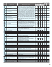
b123
Brake wait time for stopping (*3)
0.00 to 5.00 (s)
0.00 0.00 0.00 0.00 0.00
b124
Brake wait time for confi rmation (*3)
0.00 to 5.00 (s)
0.00 0.00 0.00 0.00 0.00
b125
Brake release frequency setting (*3)
0.00 to 99.99, 100.0 to 400.0 (Hz) (*1)
0.00 0.00 0.00 0.00 0.00
b126
Brake release current setting (*3)
SJ700/SJ700D: 0.0 to 2.00 x "rated current" (A)
< 75kW and over:0.0 to 1.80 x "rated current" (A)>
SJ700B: 0.0 to 1.50 x "rated current" (A)
Rated current x 1.00
b127
Braking frequency (*3)
0.00 to 99.99, 100.0 to 400.0 (Hz) (*1)
0.00 0.00 0.00 0.00 0.00
b130
Overvoltage suppression enable
00 (disabling the restraint), 01 (decelerating and stagnating),
02 (enabling acceleration with deceleration),
03 (enabling acceleration) (SJ700D only)
00 00 00 00 00
b131
Overvoltage suppression level
330 to 390 (V) (200 V class model), 660 to 780 (V) (400 V class model)
380/760 380/760 380/760 380/760 380/760
b132
Acceleration and deceleration rate
at overvoltage suppression
0.10 to 30.00 (s)
1.00 1.00 1.00 1.00 1.00
b133
Overvoltage suppression propotional gain
0.00 to 2.55
0.50 0.50 0.50 0.50 0.50
b134
Overvoltage suppression Integral time
0.000 to 9.999 / 10.00 to 63.53 (s)
0.060 0.060 0.060 0.060 0.060
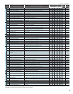
b141
Output loss detection enable (SJ700D only)
00 (disabling), 01 (enabling)
00 00 00
b142
Output loss detection sensibility (SJ700D only)
1.to 100.(%)
10. 10. 10.
b164
Automatic return to initial display (SJ700D only)
00 (disabling), 01 (enabling)
00 00 00
b166
Data Read/Write select (SJ700D only)
00 (Read/Write OK), 01 (Protected)
00 00 00
b180
Initialization trigger (SJ700D only)
00 (Initialization disable), 01 (Perform initialization)
00 00 00
(*1) 4000HF: 0.00 to 120.0 (Hz) (*2) 4000HF: 0.00 to 99.99, 100.0 to 120.0 (Hz) (*3) SJ700D (VT): Not available (no display)
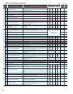
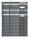
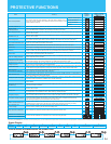
C GROUP: INTELLIGENT TERMINAL FUNCTIONS
= Allowed
= Not permitted
Code Function Name Monitored data or setting
Default Setting
Setting
during
operation
(allowed or not)
Change
during
operation
(allowed or not)
SJ700/SJ700D(CTmode)
SJ700B
-FE -FU -F -F -FU
Intelligent input terminals
C001
Terminal [1] function (*1)
01 (RV: Reverse RUN), 02 (CF1: Multispeed 1 setting), 03 (CF2: Multispeed 2
setting), 04 (CF3: Multispeed 3 setting), 05 (CF4: Multispeed 4 setting), 06 (JG:
Jogging), 07 (DB: external DC braking), 08 (SET: Set 2nd motor data), 09 (2CH:
2-stage acceleration/deceleration), 11 (FRS: free-run stop), 12 (EXT: external
trip), 13 (USP: unattended start protection), 14: (CS: commercial power source
enable), 15 (SFT: software lock), 16 (AT: analog input voltage/current select), 17
(SET3: 3rd motor control), 18 (RS: reset), 20 (STA: starting by 3-wire input), 21
(STP: stopping by 3-wire input), 22 (F/R: forward/reverse switching by 3-wire
input), 23 (PID: PID disable), 24 (PIDC: PID reset), 26 (CAS: control gain setting),
27 (UP: remote control UP function), 28 (DWN: remote control DOWN function),
29 (DWN: remote control data clearing), 31 (OPE: forcible operation), 32 (SF1:
multispeed bit 1), 33 (SF2: multispeed bit 2), 34 (SF3: multispeed bit 3), 35 (SF4:
multispeed bit 4), 36 (SF5: multispeed bit 5), 37 (SF6: multispeed bit 6), 38 (SF7:
multispeed bit 7), 39 (OLR: overload restriction selection), 40 (TL: torque limit
enable), 41 (TRQ1: torque limit selection bit 1), 42 (TRQ2: torque limit selection
bit 2), 43 (PPI: P/PI mode selection), 44 (BOK: braking confi rmation), 45 (ORT:
orientation), 46 (LAC: LAD cancellation), 47 (PCLR: clearance of position
deviation), 48 (STAT: pulse train position command input enable), 50 (ADD:
trigger for frequency addition [A145]), 51 (F-TM: forcible-terminal operation),
52 (ATR: permission of torque command input), 53 (KHC: cumulative power
clearance), 54 (SON: servo-on), 55 (FOC: pre-excitation), 56 (MI1: general-
purpose input 1), 57 (MI2: general-purpose input 2), 58 (MI3: general-purpose
input 3), 59 (MI4: general-purpose input 4), 60 (MI5: general-purpose input 5),
61 (MI6: general-purpose input 6), 62 (MI7: general-purpose input 7), 63 (MI8:
general-purpose input 8), 64 (EMR: Emergency stop) (*1), 65 (AHD: analog
command holding), 66 (CP1: multistage position settings selection 1 ), 67 (CP2:
multistage position settings selection 2), 68 (CP3: multistage position settings
selection 3), 69 (ORL: Zero-return limit function), 70 (ORG: Zero-return trigger
function), 71 (FOT: forward drive stop), 72 (ROT: reverse drive stop), 73 (SPD:
speed / position switching), 74 (PCNT: pulse counter), 75 (PCC: pulse counter
clear), 82 (PRG: EzSQ program) (SJ700D only), no (NO: no assignment)
18
(RS)
18
(RS)
18
(RS)
18
(RS)
18
(RS)
C002
Terminal [2] function
16
(AT)
16
(AT)
16
(AT)
16
(AT)
16
(AT)
C003
Terminal [3] function (*1)
06
(JG)
06
(JG)
06
(JG)
06
(JG)
03
(CF2)
C004
Terminal [4] function
11
(FRS)
11
(FRS)
11
(FRS)
11
(FRS)
02
(CF1)
C005
Terminal [5] function
09
(2CH)
09
(2CH)
09
(2CH)
09
(2CH)
01
(RV)
C006
Terminal [6] function
03
(CF2)
13
(USP)
03
(CF2)
03
(CF2)
06
(JG)
C007
Terminal [7] function
02
(CF1)
02
(CF1)
02
(CF1)
02
(CF1)
11
(FRS)
C008
Terminal [8] function
01
(RV)
01
(RV)
01
(RV)
01
(RV)
13
(USP)
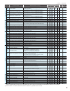
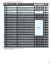
Intelligent input terminals
C011
Terminal (1) active state
00 (NO) / 01 (NC)
00 00 00 00 00
C012
Terminal (2) active state
00 (NO) / 01 (NC)
00 00 00 00 00
C013
Terminal (3) active state
00 (NO) / 01 (NC)
00 00 00 00 00
C014
Terminal (4) active state
00 (NO) / 01 (NC)
00 00 00 00 00
C015
Terminal (5) active state
00 (NO) / 01 (NC)
00 00 00 00 00
C016
Terminal (6) active state
00 (NO) / 01 (NC)
00 01 00 00 00
C017
Terminal (7) active state
00 (NO) / 01 (NC)
00 00 00 00 00
C018
Terminal (8) active state
00 (NO) / 01 (NC)
00 00 00 00 00
C019
Terminal FW active state
00 (NO) / 01 (NC)
00 00 00 00 00
(*1) When the emergency stop function is enabled (SW1 = ON), "18" (RS) and "64" (EMR) are forcibly written to parameters "C001" and "C003",
respectively. (You cannot arbitrarily write "64" to "C001".) If the SW1 signal is turned off and then turned on, "no" (no assignment) is set in parameter "C003".
(*2) 1850HF,2200HF,3150HF and 4000HF:The function is not provided.
19