


IV. Rudder and Tiller Crossbar 3. Repeat these steps on the other rudder
Assemblies assembly.
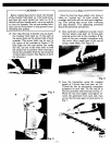
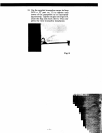
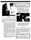
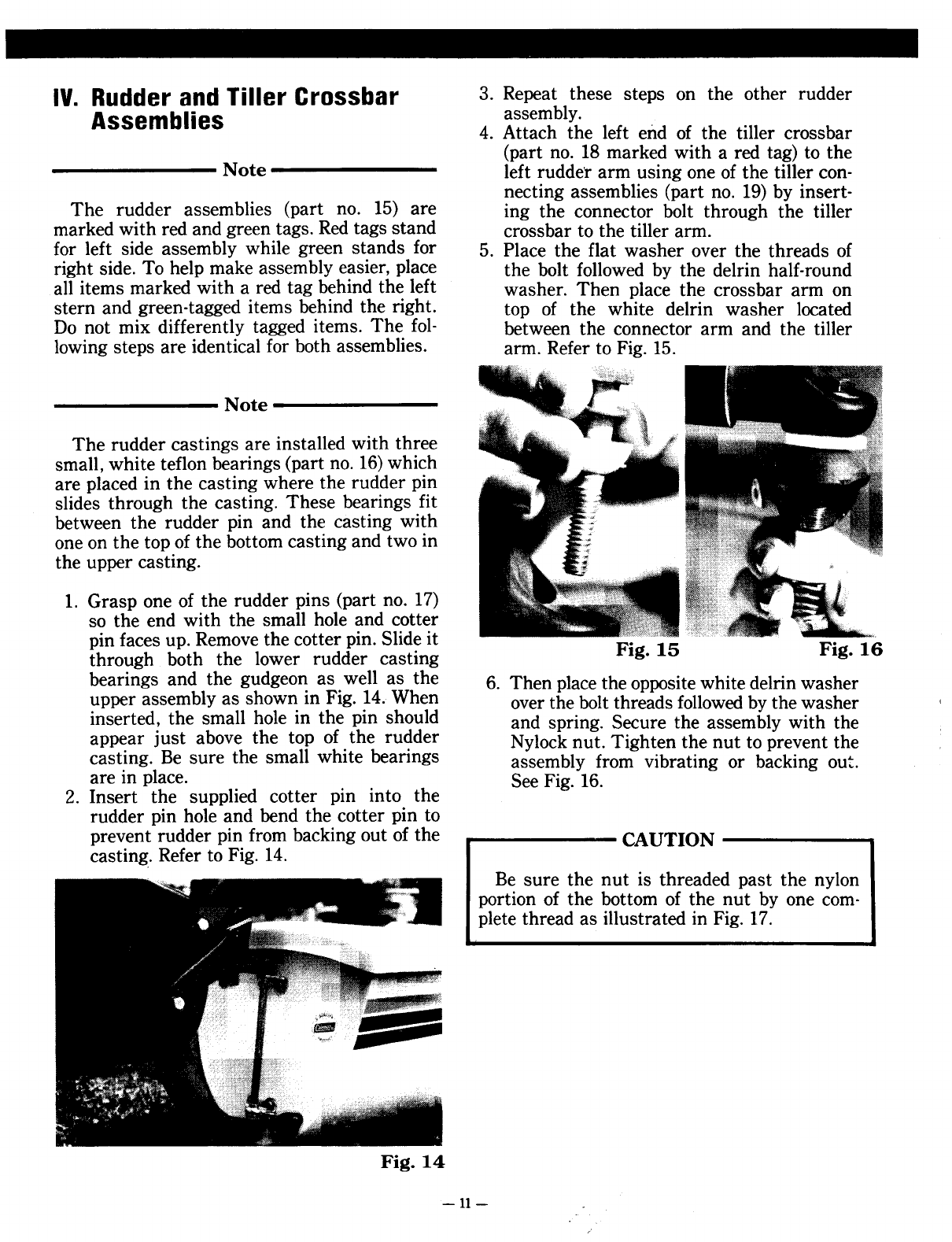
4. Attach the left end of the tiller crossbar
(part no. 18 marked with a red tag) to the
Note left rudder arm using one of the tiller con-
necting assemblies (part no. 19) by insert-
The rudder assemblies (part no. 15) are ing the connector bolt through the tiller
marked with red and green tags. Red tags stand crossbar to the tiller arm.
for left side assembly while green stands for 5. Place the flat washer over the threads of
right side. To help make assembly easier, place the bolt followed by the delrin half-round
all items marked with a red tag behind the left washer. Then place the crossbar arm on
stern and green-tagged items behind the right. top of the white delrin washer located
Do not mix differently tagged items. The fol- between the connector arm and the tiller
lowing steps are identical for both assemblies. arm. Refer to Fig. 15.
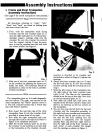
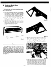
Note
The rudder castings are installed with three
small, white teflon bearings (part no. 16) which
are placed in the casting where the rudder pin
slides through the casting. These bearings fit
between the rudder pin and the casting with
one on the top of the bottom casting and two in
the upper casting.
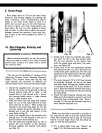
1. Grasp one of the rudder pins (part no. 17)
so the end with the small hole and cotter
pin faces up. Remove the cotter pin. Slide it F. 15 F. 16
through both the lower rudder casting Ig. Ig.
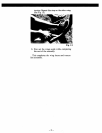
bearings and the gudgeo~ as. well as the 6. Then place the opposite white delrin washer
~pper assembly as show~ m FIg. ~4.. When over the bolt threads followed by the washer
mserted: the small hole m the pm should and spring. Secure the assembly with the
app~ar Just above the top of. the ru~der Nylock nut. Tighten the nut to prevent the
cast~ng. Be sure the small whIte bearIngs assembly from vibrating or backing out.
are m place. See Fig. 16.
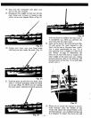
2. Insert the supplied cotter pin into the
rudder pin hole and bend the cotter pin to
prevent rudder pin from backing out of the CAUTION
casting: Refer to Fig. 14.
Be sure the nut is threaded past the nylon
portion of the bottom of the nut by one com-
plete thread as illustrated in Fig. 17.
Fig. 14
-11-