


27
9
INSTALLATION AND CONNECTIONS
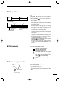
■ Wiring the EX-2714 system cable
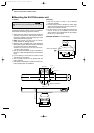
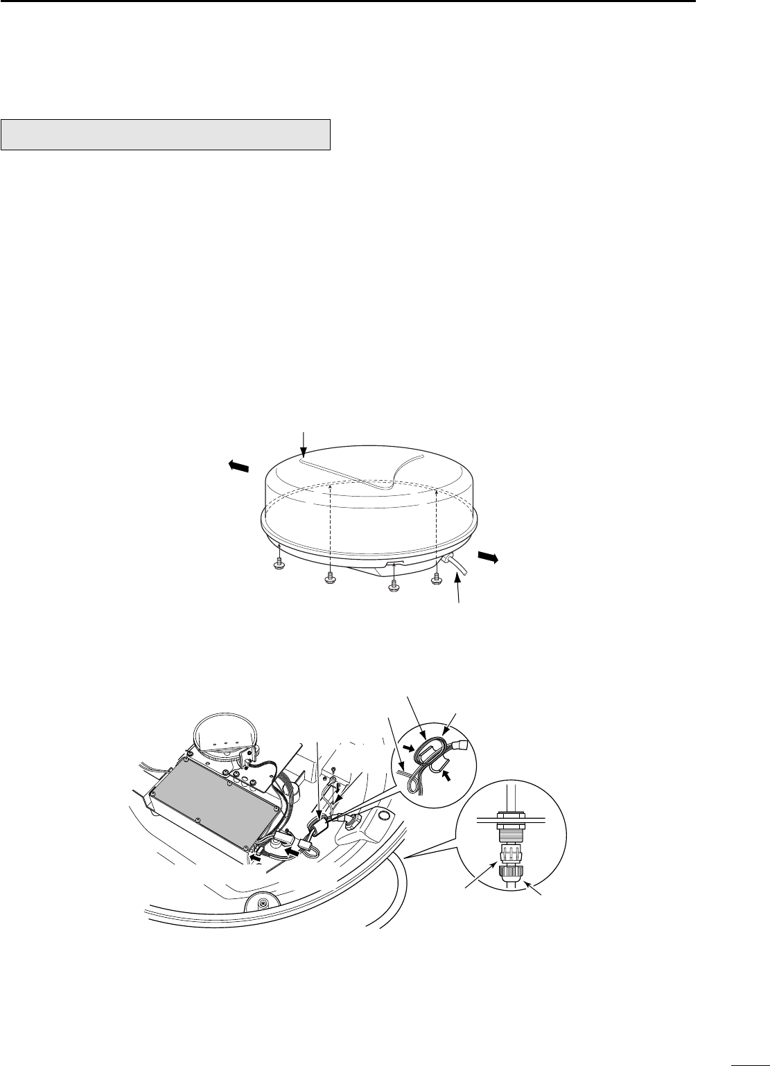
q Loosen the four bolts using a hex head wrench on
the bottom of the scanner unit, and open the unit.
w Loosen the nut on the scanner unit and pass the
system cable through the nut and sealing tube.
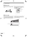
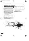
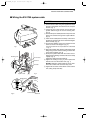
e Insert the PA cable (black and white) connector to
the PA unit connector J1. (*1; Be sure to follow the
following diagram carefully)
r Connect the shielding wire to the ground plate with
the screw as shown in the diagram.
t Clamp the system cable with the ferrite bead at-
tached near the sealing connector. Be sure to clamp
it tightly.
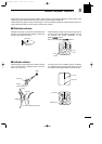
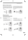
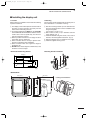
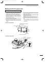
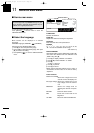
•Scanner unit disassembly
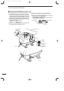
y Connect the power cable (black and red) end to the
power unit connector. (*2; Be sure to follow the fol-
lowing diagram carefully).
u Tighten the sealing-nut, then replace the radome
cover over the scanner unit.
DO NOT stretch the system cable too much, other-
wise miss contact of the connector may occur.
i Tighten the four bolts on the bottom of the scanner
unit.
• The four projections around the circumference of
the radome cover show the positions of the bolt
receptacles.
CAUTION: NEVER cut the supplied system cable.
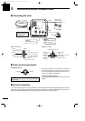
Ship’s bow direction
Face the Ω mark in the direction
of the ship’s bow.
Stern
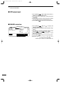
System cable
Scanner unit disassembly
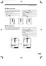
•Connect the system cable
Ferrite bead
Shielding
wire
PA cable
Power cable
Round the PA
cable twice.
Sealing tube Nut
*2; Power
connector
*1; PA cable
MR-1000R2_T2.qxd 04.2.24 10:22 Page 27