


5
2
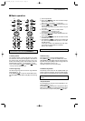
PANEL DESCRIPTION
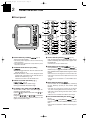
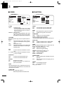
#5 COMPASS INDICATOR (pgs. 24, 39)
•GYRO : NMEA (gyro) is connected.
•COMPASS : NMEA (compass), N+1 or AUX data is
connected.
#6 EBL1/ 2 READOUTS (pgs. 15–16)
Shows the bearing of the displayed Electronic Bear-
ing Lines (EBL1 and EBL2) when the EBL is in use.
•EBL2 shows PI (!0) readout.
#7WAYPOINT/MOB READOUTS (p. 13)
➥Shows the bearing and distance to the waypoint
received from navigation equipment.
•This readout appears when the “WPT” of the FUNC-
TION menu is turned ON.
•To display the waypoint/MOB marker, bearing data
and NMEA data with 0183 format is necessary.
(p. 39)
➥Shows the bearing and distance to the MOB
(Man Over Board) event marker.
•Push [MOB]/[ ] to cancel the readout and the
symbol.
#8 POSITION/CURSOR READOUT (p. 13)
Shows your own ship or cursor latitude and longi-
tude readout when external NMEA data with 0183
format is connected.
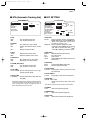
•Select ‘SHIP’ or ‘CURS’ in the “POSN DISP” of the
FUNCTION menu.
•To display the POSITION; NMEA 0183 is necessary.
•To display the CURSOR; NMEA 0183 and bearing data
are necessary.
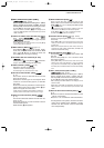
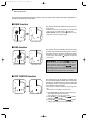
#9 CURSOR INDICATOR
Shows the bearing and distance to the cursor.
$0 VECTOR INDICATOR (p. 18)
Shows the ATA and OWN vector type.
•T: True vector
• R: Relative vector
$1 VECTOR TIME INDICATOR (p. 18)
Shows the vector interval time. Select vector time
in the “TRAIL TIME” of the VIDEO menu.
• 30 min. is applied, when ‘∞’ is selected for the vector
time.
$2 TRAILS INDICATOR (p. 12)
Shows the trail time.
•Echo remains with gradation during the trail time period
on the screen. (Except for the trail time; ∞)
•Progressing time counter starts to count the time until
the timer reaches the trail time.
$3 HEADING INDICATOR
Shows the heading bearing readout.
•The HDG readout indicates the bow of the ship’s bearing
in a clockwise direction from north.
$4 IR INDICATOR (p. 11)
Eliminates or reduces interference caused by other
radar operating nearby.
•This function is available when the “IR” in the VIDEO
menu is set to 1 or 2.
$5 ECHO STRETCH INDICATOR (p. 6)
Appears when the echo stretch function is in use.
•This function is available when the “STRETCH” of the
VIDEO menu is turned ON.
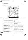
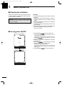
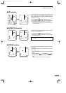
$6 CROSS LINE CURSOR
Used for measuring the bearing and distance, set-
ting the alarm zone, selecting the ATA targets, etc.
• Push [Ù Ú Ω ≈] several times to move the cursor.
$7 EBL2 (pgs. 15–16)
Used for bearing measurement. When a target is
selected, the EBL readout (#6) shows the bearing.
$8 OWN SHIP VECTOR INDICATOR
Shows the vector of your own ship.
$9 VRM 1 (pgs. 15–16)
%0 VRM 2 (pgs. 15–16)
Used for distance measurement. When a target is
selected, the VRM1/2 readout (%3) shows the dis-
tance.
%1 NORTH MARK
The north mark shows the true north direction.
%2 EBL1 (pgs. 15–16)
Used for bearing measurement. When a target is
selected, the EBL readout (#6) shows the bearing.
%3 VRM1/2 READOUTS (pgs. 15–16)
Shows the distance of the displayed Variable Range
Markers (VRM1 and VRM2) when the VRM is in
use.
• Nautical miles (NM) and kilometers (KM) can be se-
lected in the FUNCTION menu as the distance unit.
%4 ALARM INDICATOR (p. 17)
Appears when the alarm function is in use.
%5 ZOOM INDICATOR (p. 11)
Appears when the zoom function is in use.
• Push [TARGET]/[ ] and [TRAILS]/[ ] simul-
taneously to turn the function ON or OFF.
%6 TIME INDICATOR
%7 TIME INDICATOR
Shows the estimated time to the marker edge from
center of the marker with current speed.
%8 TIME INDICATOR
Shows the estimated time to the waypoint with cur-
rent speed.
MR-1000R2_T2.qxd 04.2.24 10:22 Page 5