


LXD386 — Evaluation Board for Quad T1/E1 Applications
10 Developer Manual
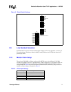
3.5 Output Enable Selection
The OE switch in switch block S4 controls the operation of the LXT386 output drivers. For normal
operation (driver outputs enabled), set the OE switch to the ON position. Setting the OE switch to
OFF forces the output drivers to the high impedance state.
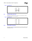
3.6 Code Selection
In Hardware mode, the MO-INT-CO switch in switch block S4 selects the line encode/decode. To
select AMI encode/decode set to the ON position. To select B8ZS/HDB3 encode/decode set to the
OFF position.
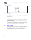
3.7 Monitoring Address Selection
Switch block S3 sets the Protected Monitoring Addresses A0 through A3. The factory default
setting is 0000 (no monitoring). See the LXT386 data sheet for details.
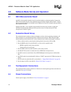
3.8 Jitter Attenuator Selection
In Hardware mode, the JASEL switch in switch block S1 selects the position of the Jitter
Attenuator in the data path:
• Transmit path = LOW
• Receive path = HIGH
• JA disabled = center