


LXD386 — Evaluation Board for Quad T1/E1 Applications Developer Manual iii
Contents
1.0 General Description ..................................................................................................5
1.1 Features ................................................................................................................5
2.0 Overview........................................................................................................................7
2.1 LXD386 Packing List.............................................................................................7
2.2 Equipment Requirements......................................................................................7
2.3 Control Modes.......................................................................................................7
2.4 Factory Settings ....................................................................................................8
3.0 Hardware Mode Set-Up and Operation..............................................................9
3.1 Power Connections ...............................................................................................9
3.2 Hardware Mode Selection.....................................................................................9
3.3 Loopback Mode Selection.....................................................................................9
3.4 Clock Edge Selection ............................................................................................9
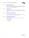
3.5 Output Enable Selection......................................................................................10
3.6 Code Selection....................................................................................................10
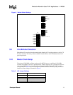
3.7 Monitoring Address Selection..............................................................................10
3.8 Jitter Attenuator Selection ...................................................................................10
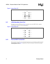
3.9 Line Buildout Selection........................................................................................11
3.10 Master Clock Setup.............................................................................................11
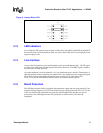
3.11 JTAG Boundary Scan Port..................................................................................12
3.12 Framer/ASIC Connection ....................................................................................12
3.13 LED Indicators.....................................................................................................13
3.14 Line Interface.......................................................................................................13
3.15 Board Protection..................................................................................................13
4.0 Software Mode Set-Up and Operation.............................................................14
4.1 i8051 Microcontroller Board ................................................................................14
4.2 Evaluation Board Set-up .....................................................................................14
4.3 Test Equipment Connections ..............................................................................14
4.4 Power Connections .............................................................................................14
4.5 Evaluation Board Software..................................................................................15
4.6 Software Installation and Start-Up.......................................................................15
4.7 Hardware Set-up Screen.....................................................................................15
4.8 Quitting the Program ...........................................................................................15
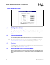
4.9 Configuration Screen...........................................................................................16
4.9.1 Communications Modes.....................................................................16
4.9.2 Registers ............................................................................................16
4.9.3 Setting Individual Transceiver Operating Modes................................16
4.9.4 Apply to all Channels..........................................................................17
4.9.5 Exit .....................................................................................................17
4.10 Registers Screen.................................................................................................18
4.10.1 Setting Registers ................................................................................18
4.10.2 Status Indicators.................................................................................18
4.10.3 Control Buttons...................................................................................18
4.10.4 Interrupts ............................................................................................18
4.10.5 Reset ..................................................................................................18