


LXD386 — Evaluation Board for Quad T1/E1 Applications
18 Developer Manual
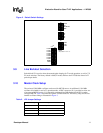
4.10 Registers Screen
4.10.1 Setting Registers
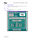
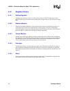
The Registers screen (see in Figure 8) allows direct control of all the LXT386 registers. Each
register is labeled by its functional name and hex address. Right click on a register name for on-line
help.
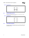
4.10.2 Status Indicators
Display boxes within the Registers screen show the state settings for individual bit positions of
each register. Each of the 4 least significant bits of these registers control the corresponding
transceiver channel, except where otherwise noted in the LXT386 specifications. The check boxes
beside the “Mode” column denote enabling of read/write step modes.
4.10.3 Control Buttons
Clicking on the “Read All” button will initiate a global read of all LXT386 registers. Clicking on
the “Read Step” and “Write Step” buttons performs the indicated action only on registers that have
the enable box checked. The “Back” button is used to return to the configuration screen, and the
“Exit” control button can be used at any time to close the software.
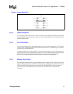
4.10.4 Interrupts
The Interrupt indicator is located in the lower right corner. This indicator will turn red whenever
there are pending interrupts in the LXT386. Interrupts are cleared by reading the corresponding
Status Monitor register. When all interrupts are cleared, the Interrupt indicator will turn Green. See
Figure 8.
4.10.5 Reset
While operating the evaluation board in Software mode, reset is accomplished by using the write
step function to write to the software reset register address 0Ah.