


Evaluation Board for Quad T1/E1 Applications — LXD386
Developer Manual 13
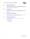
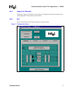
3.13 LED Indicators
Loss of Signal (LOS) status for each channel is indicated by four LEDs, labeled D3 through D6. If
the board is being used in the Software mode, the state of these LEDs will also be displayed on the
registers display screen.
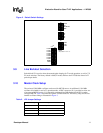
3.14 Line Interface
Access to the line interface is provided through the green and white banana jacks. The TIP signal
is routed to the white jacks for both transmit and receive directions. The RING signal is routed to
the green jacks for both directions.
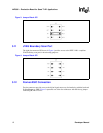
An octal transformer is used for channels 1 to 3 (one transformer port is unused). Transformers in
channel 0 and line resistors /capacitors for channels 0 to 3 are socketed for easy swapping. Jumpers
JP7 to JP14 can be used to bypass the transmit series resistors for T1 applications with
TVCC=3.3V. See the LXT386 Data Sheet for details on transmit interface options.
3.15 Board Protection
The LXD386 evaluation board is equipped with both power supply and line surge protection. Two
Transient Voltage Suppressors (TVS) are included for power supply protection (5V/3.3V). For the
T1/E1 line interface, the transmitters are protected with Schottky diodes and the receivers are
protected by series 1K
Ω input resistors. This protection is sufficient for G.703 Annex B
compliance.
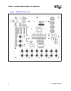
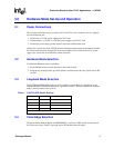
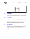
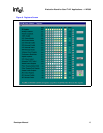
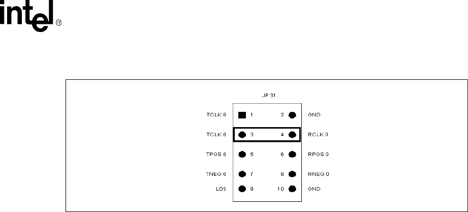
Figure 5. Jumper Block JP 31