


LXD386 — Evaluation Board for Quad T1/E1 Applications
12 Developer Manual
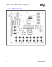
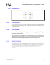
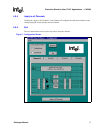
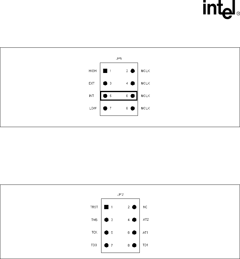
3.11 JTAG Boundary Scan Port
The eight pin connector JP2 shown in Figure 4 provides access to the IEEE 1149.1 compliant
JTAG boundary scan port for board testing purposes.
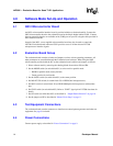
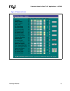
3.12 Framer/ASIC Connection
Ten pin connectors provide access to the digital signals necessary for interfacing with the back-end
Framer/Mapper or ASIC. Figure 5 represents one of the four connectors with the factory jumper
connecting RCLK to TCLK.
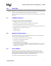
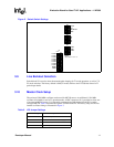
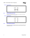
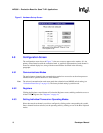
Figure 3. Jumper Block JP5
Figure 4. Jumper Block JP2