


Evaluation Board for Quad T1/E1 Applications — LXD386
Developer Manual 11
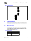
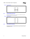
3.9 Line Buildout Selection
Switch block S2 is used to select the transmit pulse shaping for T1 mode operation, as well as T1/
E1 mode selection. The factory default is 000 (E1 mode). Refer to the LXT386 data sheet for T1
pulse shape details.
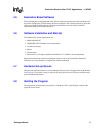
3.10 Master Clock Setup
The on-board 2.048 MHz oscillator can be used for MCLK source. An additional 1.544 MHz
oscillator is included for use in T1 operation mode. A BNC connector (J1) is provided to allow use
of an external MCLK source. J1 is internally terminated into 50
Ω. Jumper block JP5 is used to
configure MCLK. Table 2 describes the options available with JP5. The factory setup for JP5 sets
internal oscillator timing as illustrated in Figure 3.
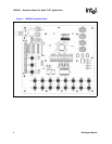
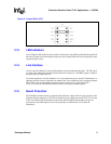
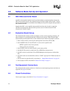
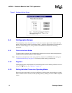
Figure 2. Default Switch Settings
NOTE:
OFF position = Low = ’0’
1 2 3 4
O
F
F
A0
A1
A2
A3
S4
1 2 3 4
O
F
F
LEN2
LEN1
LEN0
S2
1 2 3 4
S1
5 6 7 8 9 10
LOW
HIGH
LOOP0
LOOP1
LOOP2
LOOP3
LOOP4
LOOP5
LOOP6
LOOP7
MODE
JASEL
1 2 3 4
O
F
F
CLKE
OE
MO-INT-CO
MUX
S3
Table 2. JP5 Jumper Settings
JP5 Setting Operation
HIGH Data recovery mode
EXT External MCLK source at BNC (J1)
INT Internal oscillator
LOW Receiver power-down