


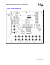

LXD386 — Evaluation Board for Quad T1/E1 Applications
14 Developer Manual
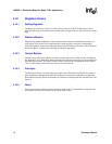
4.0 Software Mode Set-Up and Operation
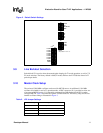
4.1 i8051 Microcontroller Board
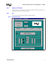
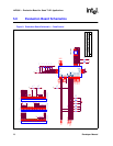
An i8051 microcontroller interface board is provided with the evaluation board kit. Connect the
i8051 microcontroller board to the evaluation board at the 96 pin header labeled CON1. Connect
the microcontroller board to an available serial (COM) port on your PC using the cable provided in
the evaluation board kit.
Instead of the i8051, a user supplied microcontroller board may also be used to control the
LXT386. Evaluation board connector CON1 provides access to all the relevant LXT386
microprocessor interface signals.
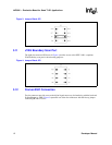
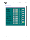
4.2 Evaluation Board Set-up
The evaluation board contains switches and jumpers to select various operating parameters. All
other parameters are controlled through the evaluation board software. When using the i8051
microcontroller provided with the kit, set the evaluation board switches and jumpers as follows:
1. Select software mode by removing the shorting blocks from sockets JP4 and JP6.
2. Set the MODE switch (in switch block S1) to select serial or parallel mode:
— HIGH for parallel mode (factory default)
— Center position for serial mode
3. Set the JASEL switch (in switch block S1) to the center position.
4. Set MO-INT-CO switch (in switch block S3) to HIGH (Intel microprocessor).
5. Set MUX switch (in switch block S3) to HIGH (Multiplexed microprocessor address/data
bus).
6. Set CLKE switch (in switch block S3). Refer to “CLKE” signal pin in LXT386 data sheet for
details.
7. Set OE switch (in switch block S3) as described in “Output Enable Selection” on page 10.
8. Set the jumper on JP5 as described in “Master Clock Setup” on page 11.
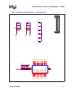
4.3 Test Equipment Connections
The evaluation board contains connectors to interface an external pattern generator and other test
equipment. See page 9 for details.
4.4 Power Connections
Connect power supply as described in “Power Connections” on page 9.