


TK-7100
10
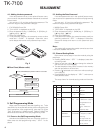
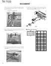
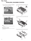
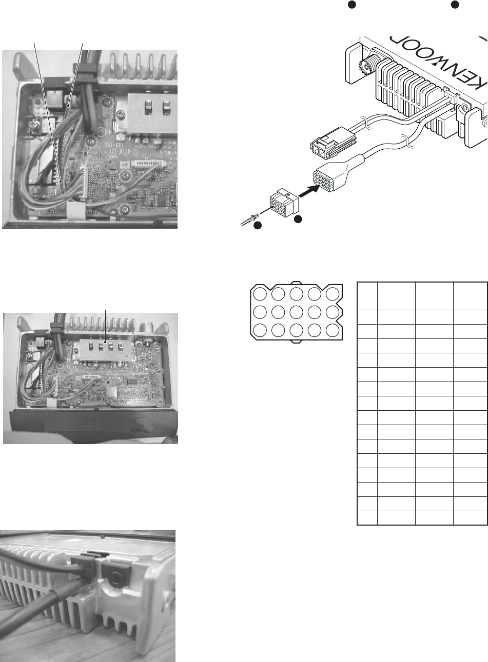
7. Align the terminal B KCT -39 cable underneath the termi-
nal A cable align the speaker cable (T07 -1082 -05) below
both KCT-39 cables.
Speaker cable
In this direction
8. Align all cable to the left side so as to avoid the Power
Module Area. Mount the shielding cover and secure it
with the five M2.6 screws.
Power module
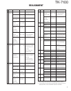
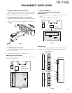
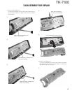
9. After everything has been properly mounted, the KCT-39
sumi tube should look similar to that as shown in the dia-
gram below.
Exterior back view of KCT-39
1
2
13
15
1
3
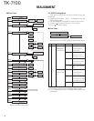
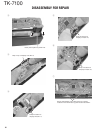
10. Connect the KCT-39 to the external accessory by insert-
ing the crimp terminal (
1
) into the square plug (
2
), both
of which are supplied with the KCT-39.
1471013
2581114
3691215
No. Color Internal Name
connector
1 Red CN2-1 SB
2 Pink CN3-1 IGN
3 Black CN2-3 GND
4 Brown CN3-3 DETO
5 Orange CN3-2 DATAI
6 Yellow CN2-8 FNC4
7 Green CN2-7 FNC3
8 Blue CN2-9 FNC5
9 Purple CN2-12 FNC8
10 Gray CN2-10 FNC6
11 White CN2-11 FNC7
12 NC NC
13 NC NC
14
Sky blue
CN2-6 FNC2
15
Turquoise
CN2-5 FNC1
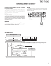
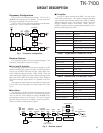
■ Accessory Port Function
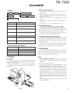
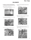
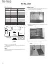
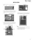
REALIGNMENT
Fig. 3