


TK-7100
3
5. INSTALLATION PLANNING – CONTROL STATIONS
5-1. Antenna system
Control station. The antenna system selection depends on
many factors and is beyond the scope of this manual. Your
KENWOOD dealer can help you select an antenna system
that will best serve your particular needs.
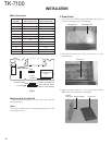
5-2. Radio location
Select a convenient location for your control station radio
which is as close as practical to the antenna cable entry point.
Secondly, use your system’s power supply (which supplies
the voltage and current required for your system). Make sure
sufficient air can flow around the radio and power supply to
allow adequate cooling.
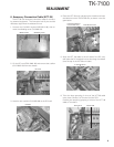
SERVICE
This radio is designed for easy servicing. Refer to the
schematic diagrams, printed circuit board views, and align-
ment procedures contained in this manual.
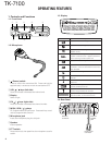
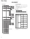
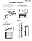
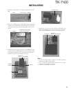
Speaker
jack cap
Power input
connector
Antenna
connector
NOTE
If you do not intend to use the 3.5-mm jack for the external
speaker, fit the supplied speaker-jack cap to stop dust and
sand from getting in.
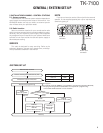
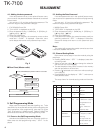
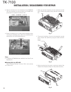
Merchandise received
License and frequency allocated by FCC
Choose the type of transceiver
Transceiver programming
KCT-39
Connection cable
KCT-18
Ignition sense cable
KCT-36
Extension cable
KDS-100
Mobile data
terminal
KGP-2A
Modem GPS receiver or
KGP-2B
Modem GPS controller
KES-3
External speaker
See page 5.
A personal computer (IBM PC or compatible), programming interface (KPG-46),
and programming software (KPG-80D)* are required for programming.
* The market of M2 uses 2.0 or more versions.
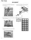
Frequency range (MHz) RF power
Type
136~162 25W M2
146~174 25W K,M
(Option)
(Option)
(Option)
(Option)(Option)
(Option)
or
Delivery
GENERAL / SYSTEM SET-UP
SYSTEM SET-UP