


TK-7100
9
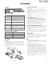
6. Accessory Connection Cable (KCT-39)
The KCT-39 is an accessory connection cable for connect-
ing external equipment. The connector has 15 pins and the
necessary signal lines are selected for use.
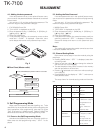
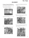
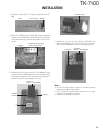
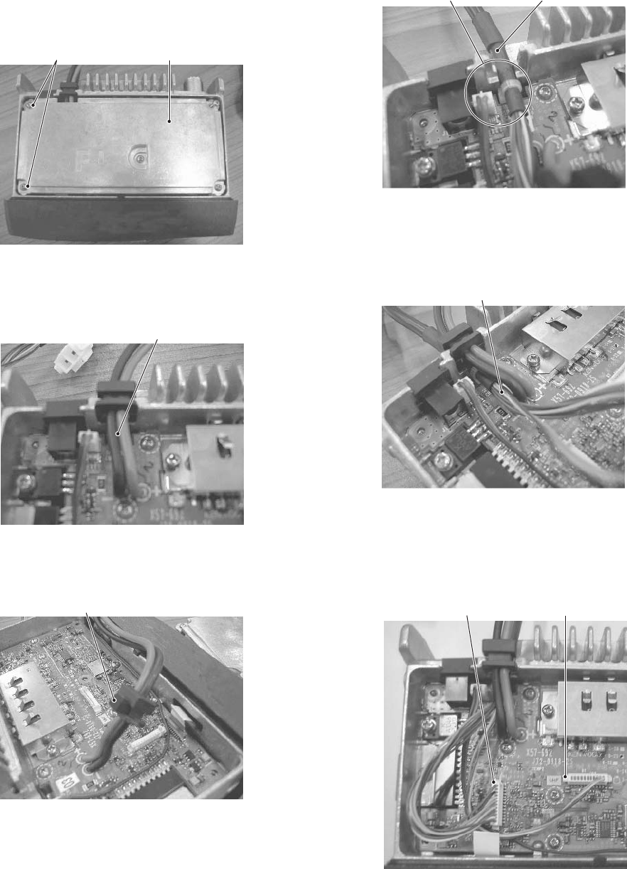
1. Unscrew the five M2.6 screws (N87-2614 -46), then re-
move the shielding cover (F10-2491-03).
2. Lift the DC cord (E30 -3448 -05) and remove the cushion
(G13 -2003 -04) from the chassis.
REALIGNMENT
M2.6 screws
Shielding cover
DC cord
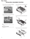
3. Attach a new cushion (G13-1960 -08) to the DC bush.
Cushion
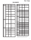
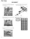
4. Place the KCT-39 sumi tube along the chassis and insert
the cable tie into the TX-RX PCB slot, as shown in the dia-
gram below.
Insert the cable tie
into the slot here
KCT-39 sumi tube
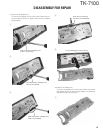
5. Align the KCT -39 cable to the left side of the DC cord,
then place the DC cord back into its slot along the chassis
(over the top of the KCT-39 sumi tube).
In this direction
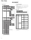
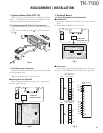
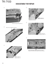
6. Twist the large grouping of wires of the KCT-39 cable
twice, then connect it to Terminal A of the PCB.
Connect the remaining grouping of wires of the KCT -39
cable to Terminal B.
Terminal A
Terminal B