


TK-7100
48
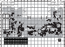
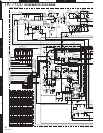
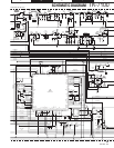
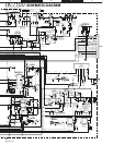
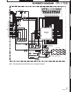
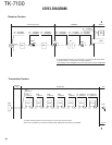
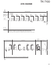
LEVEL DIAGRAM
To m
a
G2
Q351
3
IC201
IC203
Q353
XF1
7
IC202
IC202
BPF
BPF
6
8
Q40
ANT
X54-343
G2
91
To make measurements in the RF section, connect the RF level meter
.
In the RF section, use a 0.01µF coupling capacitor.
(The display shows the SSG input value required to obtain 12dB SIN
A
1
G1
2
2
S
Q352
10
Display
Unit
D
IC161
TX
-
MIC
To make measurements in the AF section, connect the AC level meter.
AG is set so that MIC input becomes 3kHz/1.5kHz (Wide/Narrow) DEV at 1kHz MOD.
D
CF1
/CF2
450kHz
7
IC203
TX-RX Unit
S
IC301
5
49.95MHz
9
IC201
G1
20
1
Center Frequency
W: –123.5dBm
N: –123.0dBm
W: –119.0dBm
N: –118.5dBm
W: –104.5dBm
N: –103.5dBm
W: –104.0dBm
N: –103.5dBm
W: 1.05Vrms
N: 0.44Vrms
W: 0.49Vrms
N: 0.20Vrms
W: –112.0dBm
N: –111.5dBm
W: –92.0dBm
N: –90.5dBm
W: –77.5dBm
N: –74.0dBm
W/N
5.0mVrms
W/N
0.10Vrms
W/N
1.40Vrms
W/N
1.16Vrms
W/N
1.26Vrms
W/N
1.04Vrms
Receiver Section
Transmitter Section