


TK-7100
34
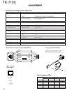
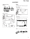
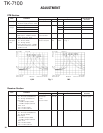
ADJUSTMENT
Receiver Section
1. Sensitivity 1) CH : RX low (Wide/Narrow) SSG ANT Check SINAD
CH : RX center (Wide/Narrow) Oscilloscope EXT. SP : 12dB or higher
CH : RX high (Wide/Narrow) AF V.M
2) SSG output Distortion meter
: –118dBm (0.28µV) (Wide)
: –116dBm (0.35µV) (Narrow)
Mod : 1kHz
Dev : ±3.0kHz (Wide)
Dev : ±1.5kHz (Narrow)
2. Squelch 9 1) CH : RX low (Wide) PC key Adjust to open the squelch
CH : RX center (Wide/Narrow)
CH : RX high (Wide)
2) SSG output
: –115dBm (0.4µV) (Wide)
: –114dBm (0.45µV) (Narrow)
Mod : 1kHz
Dev : ±3.0kHz (Wide)
Dev : ±1.5kHz (Narrow)
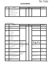
PCB Section
1. Setting 1) Power supply voltage
DC Power supply terminal : 13.6V
2. VCO lock 1) CH : TX high Digital voltmeter CV TC402 5.5V ±0.1V
voltage 2) CH : RX high TC401 5.5V ±0.1V
3) CH : TX low Check 0.7V or more
4) CH : RX low
3. IF coil 1) CH : RX center (Wide) SSG AFV L301 3.25~3.35V (DC)
2) SSG output : –53dBm (501µV) Digital voltmeter
Mod : 1kHz, Dev : 3kHz
4. RF 1) CH : RX center (Wide) Track generator ANT TC351 Adjust the BPF waveform
bandpass CH : RX low (Wide) Spectrum analyzer BPF TC352 to Fig. 1
filter CH : RX high (Wide)
2)
Track generator output : –30dBm
Connect the spectrum analyzer
to BPF terminal
Item Condition
Test equipment
Terminal
Parts Method
Specifications/
Remarks
Measurement
Adjustment
K,M Fig. 1 M2
Item Condition
Test equipment
Terminal
Parts Method
Specifications/
Remarks
Measurement
Adjustment