243
Function assignment of external terminal and control
4
PARAMETERS
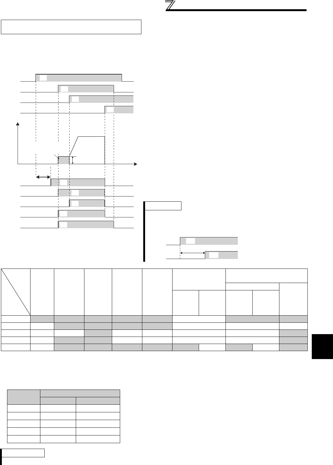
*1 Pre-excitation is made when the start signal is ON and frequency command is 0Hz.
*2 This signal turns OFF during power failure or undervoltage.
*3 There is a delay of 100ms (500ms for the 75K or higher) when the signal is ON.
*4 This signal turns ON during servo ON (LX signal is ON) under position control.
*5 Output is shutoff in conditions like a fault and when the MRS signal is ON.
Under Real sensor less vector control,
vector control
⋅ When the inverter is ready to operate, the output of the
operation ready signal (RY) is ON.
(It is also on during inverter running.)
⋅ When the inverter output frequency rises to or above the Pr.
13 Starting frequency setting, the output of the inverter running
signal (RUN) is turned ON. During an inverter stop, DC
injection brake operation, start time tuning or pre-excitation,
the output is OFF.
⋅ For the RUN2 signal, the output is ON while the inverter is
running and the start signal is ON. (For the RUN2 signal, the
output is OFF when the inverter protective function is
activated and the MRS signal is ON.)
⋅ For the RUN3 signal, the output is ON while the inverter is
running and the start signal is ON.
⋅ The RUN2 and RUN3 signals are on when the start command
is ON and even during pre-excitation with "0" set in speed
command. (Note that the RUN2 signal turns OFF during pre-
excitation by turning the LX signal ON.)
⋅ The RY2 signal turns ON at the start of pre-excitation.
The signal is ON while pre-excitation is activated even during
an inverter stop. The signal turns OFF while the output is shut
off (MRS signal).
Inverter
Status
Output
Signal
Start
Signal
is OFF
(during
stop)
Start
Signal is
ON
*1
(pre-
excitation)
Start
Signal is
ON
(during
running)
LX Signal
is ON
(pre-
excitation)
DC
Injection
Brake
Operation
(pre-
excitation)
Output Shutoff
*5
Automatic Restart after
Instantaneous Power Failure
Coasting
Restarting
Start
signal is
ON
Start
signal is
OFF
Start
signal is
ON
Start
signal is
OFF
RY ON ON ON ON ON OFF ON *2 ON
RY2 OFF
ON ON ON *3 ON OFF OFF OFF
RUN OFF OFF
ON OFF OFF OFF OFF ON
RUN2 OFF
ON ON OFF *4 OFF OFF OFF ON
RUN3 OFF
ON ON ON ON ON OFF ON OFF ON
⋅ When using the RY, RY2, RUN, RUN2 and RUN3 signals, assign
functions to Pr. 190 to Pr. 196 (output terminal selection function)
referring to the table on the left.
REMARKS
⋅ The RUN signal is assigned to the terminal RUN in the initial setting.
Time
Power
supply
STF
RH
RY
RY2
Reset
processing
ON OFF
OFF
OFF
OFF
MRS
Pr. 13
RUN
RUN2
OFF
OFF
RUN3
OFF
Output frequency
ON
ON
ON
ON
ON
ON
ON
ON
Pre-excitation
(0 speed control)
REMARKS
For pre-excitation by pre-excitation signal (LX), the RY2 signal
turns ON when 100ms has elapsed after LX signal turn ON
(500ms for the 75K or higher).
100(500)ms
LX
RY2
ON
ON
Output
signal
Pr. 190 to Pr. 196 Setting
Positive logic Negative logic
RY
11 111
RY2
33 133
RUN
0 100
RUN2
44 144
RUN3 45 145


