


SECTION SIX: Interfacing the 958 system
Page 34 958 Installation Manual, Rev. A1
3. Slide the twist lock onto the connector body.
4. Screw the connector backshell to the connector body, and tighten.
5. Install the strain- relief clamp with two screws.
6. Connect each end of the cable into the 6-pin ports at the back of the 958, or
connect one end of the cable into the 10-pin port at the back of the 941, 951, or
952.
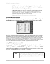
7. Turn both units on, and test for the proper cable connection: a) Press WAYPTS/
ROUTES; b) Press IMPORT/EXPORT; c) Press IMPORT DATA or EXPORT DATA; d)
Press TEST COMM. The message should read REMOTE LINK OK. If so, the
hardware connection is done and the two units can now transfer all waypoints and
routes between them.
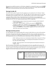
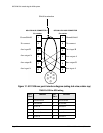
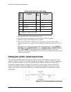
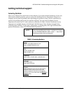
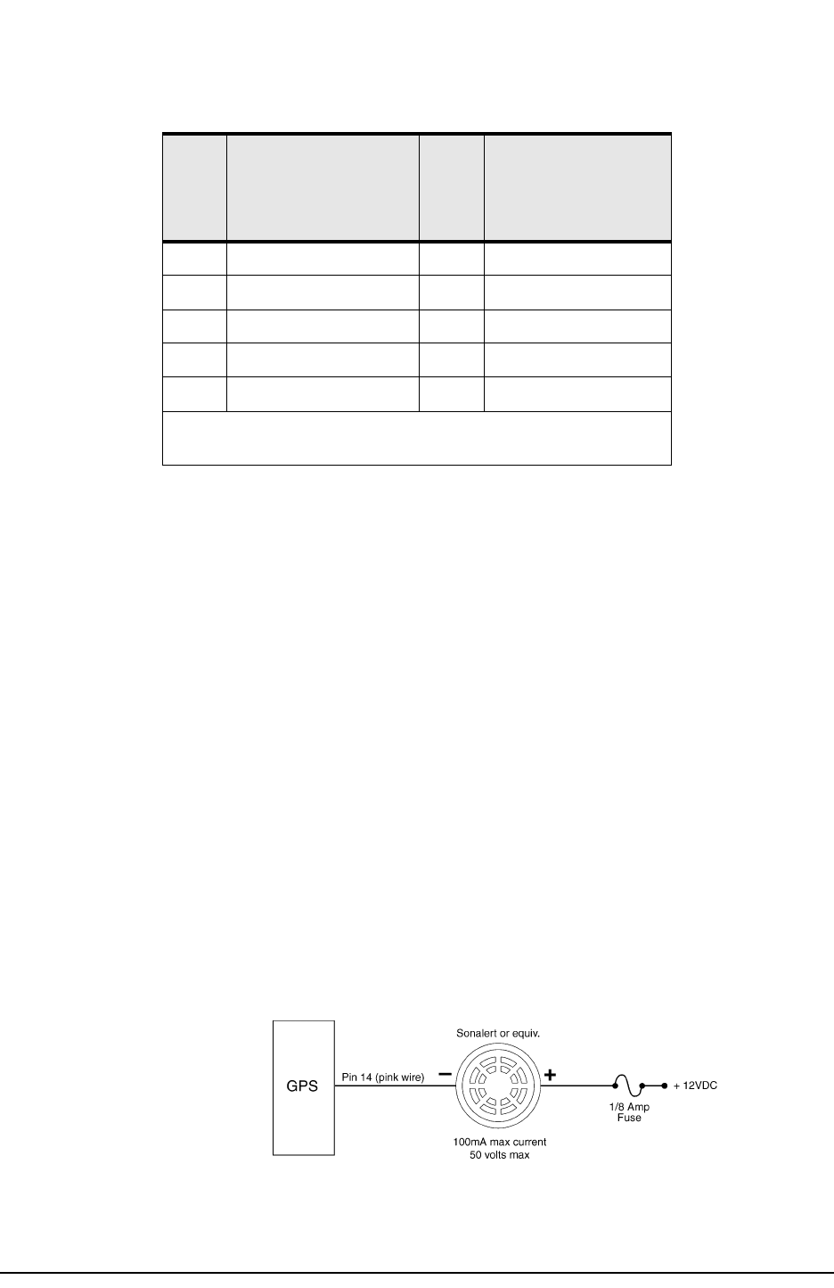
Setting the anchor-watch alarm honk
The anchor-watch alarm function is used to set the 958 to honk, in addition to beep, once you
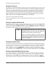
connect a honker to pin #14 on the NMEA connector. See Figure 19 below for wiring to support the
958’s external honk feature. You can use Radio Shack part number 273-060 or an equivalent. A
continuous honking sequence will begin, either when the vessel moves outside the specified
anchor-alarm radius or when the navigation source becomes unavailable—once you’ve set the
anchor-watch alarm to honk. For details, see the Northstar 958 Operator’s Manual (part number
GM958UM).
Figure 19: Pin 14 honk alarm connection
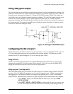
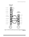
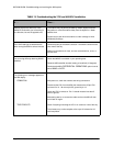
TABLE 10: 952/951/941 to 958 wiring
952
951
941
Pin #
Function 958
Pin #
Function
5 Aux In B 5 Aux Out B
6 Ground shield 1 Ground shield
7 Aux Out B 3 Aux In B
8 Aux In A 4 Aux Out A
9 Aux Out A 6 Aux In A
*Pins 1, 2, 3, 4 and 10 on the 941/951/952 aux connector, and pin 2
on the 958 aux connector, aren’t used.