


Chapter 5: Advanced Serverboard Setup
5-5
5-3 Connecting Cables
Now that the processors are installed, the next step is to connect the cables to the
serverboard. These include the data (ribbon) cables for the peripherals and control
panel and the power cables.
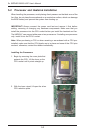
Connecting Data Cables
The cables used to transfer data from the peripheral devices have been carefully
routed in precongured systems to prevent them from blocking the ow of cooling
air that moves through the system from front to back. If you need to disconnect any
of these cables, you should take care to reroute them as they were originally after
reconnecting them (make sure the red wires connect to the pin 1 locations). If you
are conguring the system, keep the airow in mind when routing the cables.
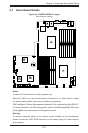
The following data cables (with their connector locations noted) should be connected.
See the serverboard layout diagram in this chapter for connector locations.
•DVD-ROM drive cable (USB4)
•SAS cables (connect to optional UIO SAS controller card)
•Control Panel cable (JF1, see next page)
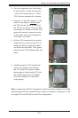
Connecting Power Cables
The H8DGU-F has a 20-pin primary power supply connector designated "JPW1"
for connection to the ATX power supply. Connect the appropriate connector from
the power supply to JPW1 to supply power to the serverboard. See the Connector
Denitions section in this chapter for power connector pin denitions.
In addition, your power supply must be connected to the 8-pin Processor Power
connectors at JPW2 and JPW3.
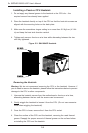
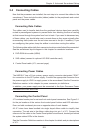
Connecting the Control Panel
JF1 contains header pins for various front control panel connectors. See Figure 5-1
for the pin locations of the various front control panel buttons and LED indicators.
Even and odd numbered pins are on opposite sides of each header.
All JF1 wires have been bundled into single keyed ribbon cable to simplify their
connection. The red wire in the ribbon cable plugs into pin 1 of JF1. Connect the
other end of the cable to the Control Panel printed circuit board, located just behind
the system status LEDs in the chassis.
See the Connector Denitions section in this chapter for details and pin descriptions
of JF1.