


5-18
A+ SERVER 2022G-URF User's Manual
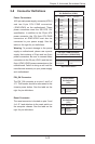
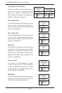
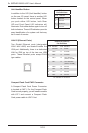
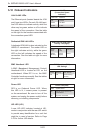
Compact Flash Card PWR Connector
A Compact Flash Card Power Connector
is located at JWF1. For the Compact Flash
Card to work properly, you will need to enable
with JCF1 and connect a Compact Flash
Card power cable to JWF1 rst.
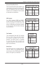
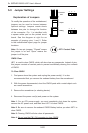
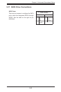
UID Button
Pin Denitions
Pin# Denition
1 Ground
2 Ground
3 Button In
4 Ground
Unit Identier Button
In addition to the UID (Unit Identier) button
on the rear I/O panel, there is another UID
button located on the control panel. When
you push either UID button, both Rear
UID and Front Panel UID Indicators will
illuminate. Push either button again to turn off
both indicators. These UID indicators provide
easy identication of a system unit that may
be in need of service.
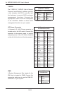
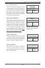
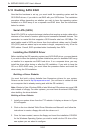
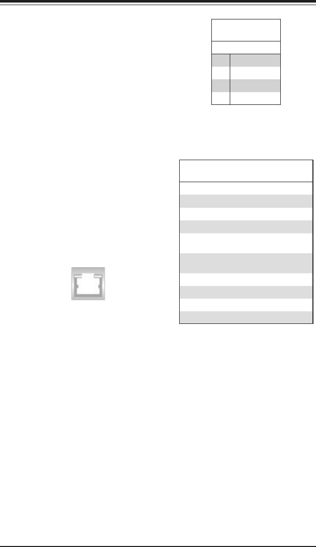
LAN1/2 (Ethernet Ports)
Two Gigabit Ethernet ports (designated
LAN1 and LAN2) are located beside the
VGA port. Additionally, there is a dedicated
LAN for IPMI on top of the two rear USB
ports. These Ethernet ports accept RJ45
type cables.
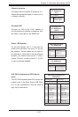
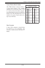
LAN Ports (LAN1/2)
Pin Denition
Pin# Denition Pin# Denition
1 P2V5SB 10 SGND
2 TD0+ 11 Act LED
3 TD0- 12 P3V3SB
4 TD1+ 13 Link 100 LED
(Yellow, +3V3SB)
5 TD1- 14 Link 1000 LED
(Yellow, +3V3SB)
6 TD2+ 15 Ground
7 TD2- 16 Ground
8 TD3+ 17 Ground
9 TD3- 18 Ground
NC indicates no connection.