


Chapter 5: Advanced Serverboard Setup
5-17
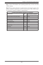
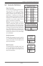
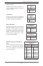
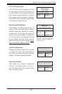
ATX PS/2 Keyboard and PS/2 Mouse
Ports
The ATX PS/2 keyboard and PS/2 mouse are
located next to the Back Panel USB Ports
0~3 on the motherboard. See the table at
right for pin denitions.
PS/2 Keyboard/Mouse Pin
Denitions
PS2 Keyboard PS2 Mouse
Pin# Denition Pin# Denition
1 KB Data 1 Mouse Data
2 No
Connection
2 No
Connection
3 Ground 3 Ground
4 Mouse/KB
VCC (+5V)
4 Mouse/KB
VCC (+5V)
5 KB Clock 5 Mouse Clock
6 No
Connection
6 No
Connection
VCC: with 1.5A PTC (current limit)
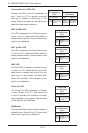
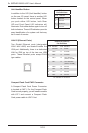
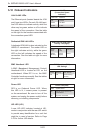
Power LED/Speaker
On the JD1 header, pins 1~3 are used for
power LED indication, and pins 4-7 are for
the speaker. See the tables on the right for
pin denitions. If you wish to use the onboard
speaker, you should close pins 6~7 with a
jumper. Connect a cable to pins 4~7 of JD1
to use an external speaker.
Speaker Connector
Pin Denitions
Pin Setting Denition
Pins 4~7 External Speaker
Pins 6~7 Internal Speaker
PWR LED Connector
Pin Denitions
Pin Setting Denition
Pin 1 Anode (+)
Pin2 Cathode (-)
Pin3 NA
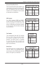
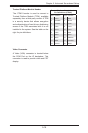
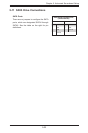
Chassis Intrusion
A Chassis Intrusion header is located at JL1.
Attach the appropriate cable to inform you of
a chassis intrusion.
Chassis Intrusion
Pin Denitions
(JL1)
Pin# Denition
1 Battery voltage
2 Intrusion signal
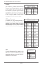
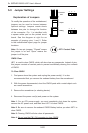
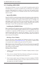
Overheat LED
Connect an LED to the JOH1 header to
provide warning of chassis overheating. See
the table on the right for pin denitions.
Overheat LED
Pin Denitions
(JOH1)
Pin# Denition
1 3.3V
2 OH Active