


5-16
A+ SERVER 2022G-URF User's Manual
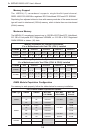
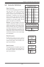
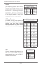
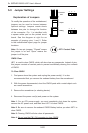
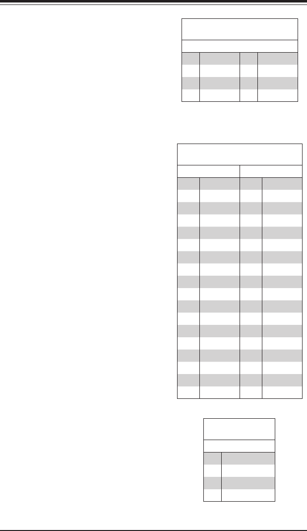
T-SGPIO
The T-SGPIO1/ T-SGPIO2 (Serial General
Purpose Input/Output) headers provide
a bus between the SATA controller and
the backpane to provide SATA enclosure
management functions. Connect the
appropriate cable from the backplane
to the T-SGPIO1 header to utilize SATA
management functions on your system.
SGPIO Header Pin Denitions
(T-SGPIO1/T-SGPIO2)
Pin# Denition Pin# Denition
1 NC 2 Data In
3 Ground 4 Data Out
5 Load 6 Ground
7 Clock 8 NC
Note: NC indicates no connection.
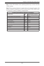
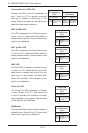
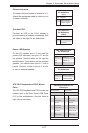
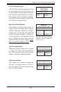
UIO Power Connector
A Universal I/O (UIO) Power connector is
located next to the UID switch. Connect this
connector to the power supply to provide
adequate power to the UIO device installed
on the slot for this device to function properly.
UIO Power Connector
Pin Denitions (UIOP)
Pin# Denition Pin# Denition
B1 5V_1 A1 3V3_1
B2 5V_2 A2 3V3_2
B3 5V_3 A3 3V3_3
B4 5V_4 A4 3V3_4
B5 5V_5 A5 3V3_5
B6 5V_6 A6 3V3_6
B7 5V_7 A7 3V3_7
B8 5V_8 A8 3V3_8
B9 5V_9 A9 3V3_9
B10 5V_10 A10 3V3_10
B11 N12V A11 3V3
B12 3V3_STBY A12 3V3
B13 3V3_STBY A13 P12V_2
B14 GND A14 P12V
B15 GND A15 P12V
B16 GND_1 A16 P12V
B17 GND_2 A17 P12V
B18 GND_3 A18 GND_7
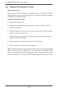
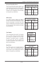
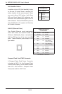
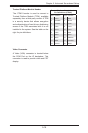
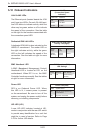
IPMB
A System Management Bus header for the
IPMI slot is located at IPMB. Connect the
appropriate cable here to use the IPMB I2C
connection on your system.
IPMB
Pin Denitions
Pin# Denition
1 Data
2 Ground
3 Clock
4 No Connection