


Chapter 2: Overview
724-746-5500 | blackbox.com
11
devices; and control these devices using the specified services (for example, Telnet, HHTPS, RDP, IPMI, Serial over LAN, Power Control). An
authorized User also has a limited view of the Management Console and can only access authorized configured devices and review port logs.
In this manual, when the term user (lower case) is used, it refers to both the above classes of users. This document also uses the term remote users
to describe users who are not on the same LAN segment as the console server. These remote users may be Users, who are on the road connecting
to managed devices over the public Internet, or it may be an Administrator in another office connecting to the console server itself over the
enterprise VPN, or the remote user may be in the same room or the same office but connected on a separate VLAN than the console server.
2.4 Management Console
The Management Console provides a view of the console server and all the connected devices.
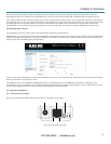
Administrators can use any browser to log into the Management Console either locally or from a remote location. They can then use Management
Console to manage the console server, the users, the serial ports and serially connected devices, network connected hosts, and connected power
devices; and to view associated logs and configure alerts.
Figure 2-1. Login screen for the management console.
A User can also use the Management Console, but has limited menu access to control select devices, review their logs, and access them using the
built-in java terminal or control power to them.
The console server runs an embedded Linux® operating system, and experienced Linux and UNIX® users may prefer to configure it at the
command line. To get command line access, connect through a terminal emulator or communications program to the console serial port; connect
via ssh or telnet through the LAN; or connect through an SSH tunneling to the console server.
2.5 Hardware Description
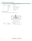
2.5.1 LES1101A Front Panel
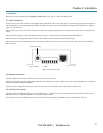
Figure 2-2 shows the front panel of the LES1101A. Table 2-1 describes its components.
Figure 2-2. LES1101A front panel.
1 2 3
5 4
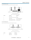
1 2 3
1 2 3