


Installation and Configuration Manual 13
Installation (Short Stem)
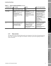
Installation (Short Stem) Electrical ConnectionsInstallation (Long Stem)Introduction
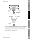
The pocket geometry must be consistent with 2" schedule 40 tube in both internal diameter and
minimum wall thickness, i.e.:
• Internal diameter: 2.1" (52.5 mm)
• Wall thickness : minimum 0.15" (3.912 mm)
Weld neck or slip-on flanges may be used, according to the flange rating selected. However, for
higher rated flanges, only slip-on flanges may give the necessary clearances.
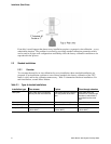
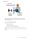
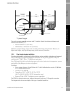
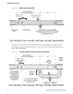
2.3.6 Flow-through chamber installation
Flow-through chambers are fabricated by Micro Motion, and are available with either weld prepared
ends or with flange or compression fittings for connection into the process pipe lines. They are
available with 1" NB, 2" NB, or 3" NB inlet and outlet pipes.
Note: The length of the inlet and outlet pipes must not be altered, otherwise the temperature response
and stability of the fitting may be adversely affected.
Conditions:
• Flow: constant, between 10 and 30 l/min for 2" sch 40 calibration bore section, 5–300 l/min
for 3" sch 80 calibration bore.
• Viscosity: 0.5 to 1000 cP
• Temperature: -50 °C to 200 °C (–58 °F to 392 °F)
[-40 °C to 200 °C (-40 °F to 392 °F) in hazardous areas]
• Pressure: 70 bar @ 204 °C, subject to process connections.
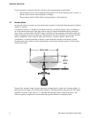
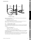
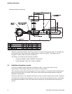
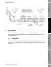
The PT100 is a direct insertion type, without a thermowell, and uses a ¾" Swagelok connection.
The diagram below shows an example of this type of standard installation.
“T” piece Flanged
D
4” or larger;
horizontal
or vertical
6.9”
(175 mm ±2
mm)
7.75”
(197 mm)
2” (52.3 mm)
wall thickness
at least
0.15” (3.912 mm)
2” Schedule 40
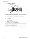
PFA
ring
circlip
0.47” (12 mm)
4.37” (111 mm)