


Installation and Configuration Manual 43
Calibration Check
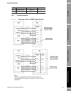
Calibration Check General MaintenanceUsing 795X Processing Electronics
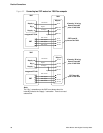
6.3 In-line calibration
6.3.1 Viscosity
The 7827 meter is calibrated to operate in installations where the boundary formed by the surrounding
metalwork is at a distance away where it does not influence the viscosity reading from the meter. If
the installation is such that an error in viscosity is seen due to the proximity of the metalwork to the
tines, an in-line calibration is needed to correct for this source of error.
To perform an in-line calibration it is necessary to know the actual dynamic viscosity and temperature
of the calibrating fluid along with both time periods from the meter. The fluid dynamic viscosity at
these operating conditions may be determined by using a suitable conventional viscometer/rheometer
or by measuring the fluid's kinematic viscosity and multiplying by the fluid's actual density (in g/cc).
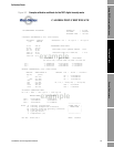
The procedure for calculating the new calibration coefficients V1' for the particular viscosity range
currently selected is that shown below:
• where V1' = New V1 calibration coefficient for current viscosity range and installation only
• V1 = Original V1 calibration coefficient for current viscosity range
• Q = meter quality factor value in calibration fluid and installation
• η
actual
= Actual fluid viscosity (measured from a standard) – (cP)
• η
calc
= Calculated fluid viscosity (using original coefficients and Q below) – (cP)
Note: The value of V1' is now used in the general viscosity equation in the 795x replacing the original
values of V1 on the calibration certificate for this application only and for this viscosity range only.
If the process viscosity is variable, the calibration should be tested at the maximum, minimum, and
mid-point values of the process viscosity range, to check that the V1 correction is sufficient.
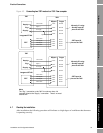
6.3.2 Density
The 7827 meter is calibrated to operate in installations where the boundary formed by the surrounding
metalwork is at a distance away where it does not influence the density reading from the meter. If the
installation is such that an error in density is seen due to the proximity of the metalwork to the tines,
an in-line calibration is needed to correct for this source of error.
To perform an in-line calibration it is necessary to know the actual density and temperature of the
calibrating fluid along with the time period B from the meter. The fluid density at these operating
conditions may be determined by using using one of the methods outlined below:
For stable liquids
Draw off a sample of the liquid into a suitable container, at the same time note the density and the
operating temperature. Measure the density of the sample under defined laboratory conditions using a
hydrometer or other suitable equipment.
Note: It is essential that you have a good understanding of the physical properties (temperature
coefficient, etc.) of the liquid and that tables of such data are available when using this method.
V1' = V1 + Q
2
* ( η
actual
- η
calc
)