


Installation and Configuration Manual 53
General Maintenance
Calibration Check General MaintenanceUsing 795X Processing Electronics
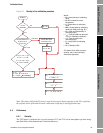
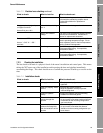
7.3.3 Checking the installation
The last check to be made is a physical check of the meter's installation and wetted parts. This means
taking the 7827 meter out of the installation and inspecting the tines and pipeline immediately
surrounding the flange. This check should serve to confirm the presence of build-up or erosion on the
tines.
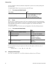
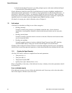
> 60 mA Electronics drawing excessive current: There is
a fault with the maintaining amplifier board.
Contact Micro Motion for replacement
electronics.
Voltage at viscosity signal input
on Signal Converter:
Across PL2, pins 1 & 2
5 V to 15 V dc, switching
to 0 V
Correct waveform being sent from the meter.
High or low constant
voltage
The meter is not supplying the Signal Converter
with the correct waveform. Contact Micro
Motion for replacement electronics.
Resistance at PRT:
Across " + SIG " & " - SIG "
terminals
80 Ω to 160 Ω Correct resistance lower and upper limits for
meter's operating temperature range. For an
exact resistance value for the line temperature,
see the Product Data appendix.
Out of range The PRT has gone open circuit:
Check associated wiring. If unrepairable,
contact Micro Motion.
0 Ω The PRT wiring has short circuited:
Check associated wiring. If unrepairable,
contact Micro Motion.
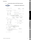
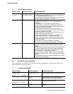
Table 7-4 Installation checks
What to check: What to look for: What to check next:
Presence of bubbles Leaky pipework. • Flanging correctly aligned, sealed and
tightened.
Listen for "popping" inside
the line.
• Increase the pipeline pressure.
• Align the pipework correctly to prevent
vortices being shed.
Pumps or agitators
nearby.
• Pumps and agitators may be generating
bubbles from dissolved gases.
Flow rate Determine the flow
velocity through the
pipeline.
• Refer to the appropriate Installation chapter
for your meter to see what maximum flowrate
is allowable for the mounting configuration
you have chosen.
Determine the distance
between the flange face
and the inside bore of the
pipeline.
• Refer to the appropriate Installation chapter
for your meter to see what this distance
should be for the mounting configuration you
have chosen.
Table 7-3 Electrical error checking continued
What to check: What to look for: What to check next: