


16 Micro Motion 7827 Digital Viscosity Meter
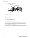
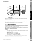
Installation (Short Stem)
Where it is necessary to install the viscometer in a by-pass (either using the free stream installation in
a 4" diameter horizontal by-pass, or a flow-through chamber), flow may be maintained using pressure
drop, pitot scoop, or by a sample pump. Where a pump is used, the pump should be upstream of the
viscometer.
Entrained gas
Gas pockets can disrupt the measurement. A brief disruption in the signal caused by transient gas
pockets can be negated in the signal conditioning software, but more frequent disruptions or serious
gas entrainment must be avoided. This can be achieved by observing the following conditions:
• Keep pipe lines fully flooded at all times
• Vent any gas prior to the viscometer
• Avoid sudden pressure drops or temperature changes which may cause dissolved gases to
break out of the fluid
• Maintain a back pressure on the system sufficient to prevent gas break out (e.g. back pressure
equivalent to twice the ‘head loss’ plus twice the vapor pressure)
• Maintain flow velocity at the sensor within the specified limits.
Solids contamination
• Avoid sudden changes of velocity that may cause sedimentation.
• Install the viscometer far enough downstream from any pipework configuration which may
cause centrifuging of solids (e.g. bends).
• Maintain flow velocity at the sensor within the specified limits.
• Use filtration if necessary.
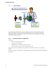
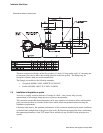
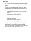
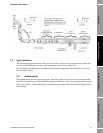
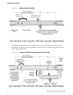
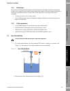
The diagram below illustrates some of the principles outlined in this section. It shows a free-stream
viscometer installation with an additional sample take off. The position of both is such that the static
mixing (which could be caused by pump discharge or partially closed valve), has negated the adverse
effects of bends and established laminar flow, and has ensured that the fluid is thoroughly mixed and
thus of uniform composition and temperature. The ideal place for a free stream or “T” piece
installation, or for the by-pass take off point is where the flow has just begun to be laminar.
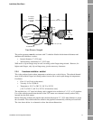
Note: The insulation extends upstream and downstream far enough to prevent conduction losses in the
pipe walls from degrading the temperature conditioning of the fluid at the sensor.