


Installation and Configuration Manual 15
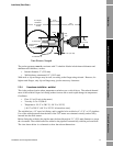
Installation (Short Stem)
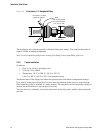
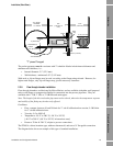
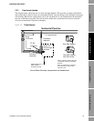
Installation (Short Stem) Electrical ConnectionsInstallation (Long Stem)Introduction
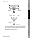
You must first select a location which serves the application objective; e.g. installed close to the point
of control. Then, consideration can be given to fluid conditioning at that point. Where the application
requirements allow a degree of tolerance in the point chosen for installation, the installation may be
able to take advantage of natural flow conditioning.
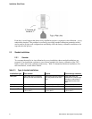
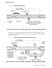
The choice of mechanical installation (free stream, “T” piece or flow-through chamber) will be
dictated partly by application needs and partly by the fluid conditions, such as:
• Condition of fluid at the sensor
• Thermal effects
• Flow rate
•Entrained gas
• Solids contamination
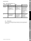
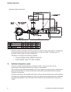
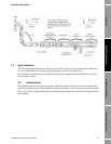
Fluid at the sensor
The fluid in the effective zone of the 7827 meter must be of uniform composition and at uniform
temperature. It must be representative of the fluid flow as a whole.
This is achieved either by mixing of the fluid either using a static inline mixer or taking advantage of
any natural pipe condition that tends to cause mixing, such as pump discharge, partially open valves.
The viscometer should be installed downstream where the flow is just returning to laminar flow
conditions.
Thermal effects
Avoid temperature gradients in the fluid and in the pipe work and fittings immediately upstream and
downstream of the viscometer.
Always insulate the viscometer and surrounding pipework thoroughly. Insulation must be at least
1" (25 mm) of rockwool, preferably 2" (50 mm) (or equivalent insulating heat jacket) and enclosed in
a sealed protective casing to prevent moisture ingress, air circulation, and crushing of the insulation.
Special insulation jackets are available from Micro Motion for the flow-through chambers, which,
because of the low volumetric flow rates and hence low heat flow, are more vulnerable to temperature
effects.
Avoid direct heating or cooling of the viscometer and associated pipe work upstream and downstream
that is likely to create temperature gradients. If it is necessary to provide protection against cooling
due to loss of flow, electrical trace heating may be applied, provided it is thermostatically controlled
and the thermostat is set to operate below the minimum operating temperature of the system.
Where flow-through chambers are used and where base (or referred) viscosity is required and the
behavior of the fluid is such that the temperature of the sample flow will require controlling, heat
exchangers should be fitted upstream a sufficient distance from the chamber so that the fluid
temperature is relatively stable. Insulation should be extended from the viscometer to the outlet from
the heat exchanger. Fluid heat exchangers should be controlled by modulating the flow rate of the heat
exchange fluid and not by modulating the sample flow rate.
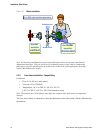
Flow rate
Flow rates and velocities should be maintained relatively constant within the limits given. The fluid
flow provides a steady heat flow into the viscometer section, and the flow rate influences the self
cleaning of the sensor and the dissipation of bubbles and solid contaminants.