


Installation and Configuration Manual 17
Installation (Short Stem)
Installation (Short Stem) Electrical ConnectionsInstallation (Long Stem)Introduction
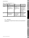
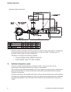
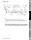
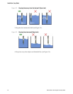
2.5 Typical installations
The following diagrams illustrate some typical solutions for line viscosity measurement, simple base
viscosity referral and base viscosity using temperature control of the sample flow.
In all examples, the fluid flow is assumed to be uniform in composition and temperature as it enters
the viscometer section.
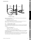
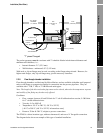
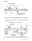
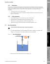
2.5.1 Jacketed pipeline
The diagram below shows a jacketed pipeline. The heating fluid in the jacket will cause temperature
gradients, and therefore it is discontinued through the viscometer section. If protection against cooling
due to loss of flow is required through the unjacketed section then it must be provided using electrical
trace heating.