


52 Micro Motion 7827 Digital Viscosity Meter
General Maintenance
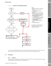
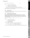
7.3.2 Checking the power consumption
A lot of information is gained from checking the power consumption at various parts of the circuit
between Signal Converter and meter.
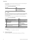
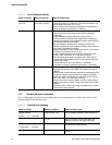
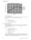
Table 7-2 Error checking for density
What to check: What to look for: What to check next:
Indicated density
(loc 014)
Reading unsteady
(more than ±1kg/m
3
)
• Time period τ
B
(below).
• Is the signal input 0V connection (PL2 pin2) connected to 0V
on the Signal Converter (PL1 pin 4)?
• If the reading is still unsteady, the installation is probably the
cause of the fault (see Section 7.3.3 below).
Reading out of limits • Do the calibration coefficients for density programmed into the
Signal Converter match those on your factory calibration
certificate?
• Is the temperature input FREE and reading correct)?
• Do the calibration coefficients for temperature correction on
density programmed into the Signal Converter match those on
your factory calibration certificate?
• Do the calibration coefficients for viscosity correction on
density programmed into the Signal Converter match those on
your factory calibration certificate?
• Have you selected "VOS correction" and left the value of fluid
VOS) set to an incorrect value, e.g. 0?
• Is the indicated density greater than the “density high limit”
value? - SET limit value to "1.00E+99" to find out.
• Has the fluid density actually changed to the value shown?
Compare a sample measured with a known density standard
with the 7827 meter.
• Product build-up on tines (see Section 7.3.3 below).
• Corrosion or erosion on the tines (see Section 7.3.3 below).
Reading not updating • Is the density value FREE on the Signal Converter?
• Are both time period values FREE in the Signal Converter?
(Below)
• Are the temp corrected density, viscosity corrected density and
uncorrected density values all free in the signal convereter?
• Is the line density greater than the “density high limit” value? -
SET limit value to "1.00E+99" to find out.
• Check connections between 7950/1 and 7827 meter (below).
• Meter not powered correctly: Check consumption at the meter
(below).
• Fault with 7950/1: Refer to the 7950/1 Handbook, then contact
Micro Motion if fault persists.
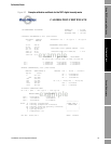
Table 7-3 Electrical error checking
What to check: What to look for: What to check next:
Voltage at meter:
Across " + " & " - " terminals
22.8 V to 25.2 V dc Correct voltage supplied to meter electronics.
0 V dc There is an open circuit on the power line
between the meter and Signal Converter.
Current at meter:
In series with " + " terminal
0 mA Electronics not drawing current:
Check wiring for open circuits.
25 mA to 40 mA Electronics drawing the correct amount of
current.