


Installation and Configuration Manual 33
Electrical Connections
Installation (Short Stem) Electrical ConnectionsInstallation (Long Stem)Introduction Installation (Short Stem) Electrical ConnectionsInstallation (Long Stem)Introduction Installation (Short Stem) Electrical ConnectionsInstallation (Long Stem)Introduction Installation (Short Stem) Electrical ConnectionsInstallation (Long Stem)Introduction
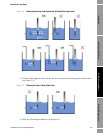
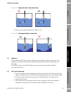
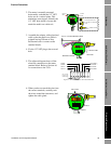
2. The meter is normally mounted
horizontally such that the 1/2” NPT
holes are on a vertical plane. This
minimizes water ingress. Identify the
1/2" NPT hole which is lowest and
attach the multi-core cable to it.
3. Assemble the adaptor, cable gland and
cable so that the multi-core cable is
gripped leaving 200 mm of free,
unscreened wire to connect to the
terminal blocks.
4. Fix the 1/2" NPT plug to the un-used
hole.
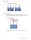
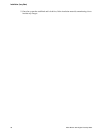
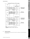
5. The adjacent diagram shows all the
electrical connections to the meter
terminal block. Refer to Section 4.6
for connections to the 795x.
6. When you have screwed the wires into
the correct terminals, carefully tuck
the wires around the electronics, and
tighten the cable gland.
1/2" NPT
HOLE
1
/2" NPT
HOLE
1/2" NPT PLUG Exd IIC
1/2" TO M20 x 1 ADAPTOR
E
xd IIC
M20 x 1 CABLE GLAND
Exd IIC
SUPP LY SIG
+
+
PR
T
TB3 TB1
TB2
200 mm OF UNSCREENED WIRE
TERMINAL BOARD
A
DAPTOR
CABLE GLAND
SU
PPLY
S
I
G
+
+
PRT
SIGNAL -
SIGNAL +
SUPPLY -
SUPPLY +
PRT POWER +
PRT SIGNAL +
PRT SIGNAL -
PRT POWER -
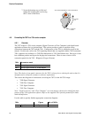
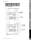
Figure 3.1:
Electrical connections to 7827 main terminal bloc
k
Note: “Supply-”
& “Signal -” are
linked internally
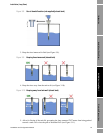
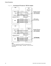
TB3
NEST WIRES
PRT
Term 1
T
erm 8
SUPPLY SIG
TB1
+ - + -