


Installation and Configuration Manual 19
Installation (Short Stem)
Installation (Short Stem) Electrical ConnectionsInstallation (Long Stem)Introduction
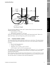
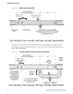
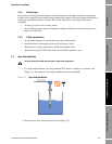
2.5.2 Flow-through chamber
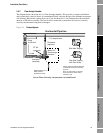
The diagram below shows the use of a flow-through chamber. This provides a compact installation
and is particularly suited to flows of contaminated fluids, since the design of the chamber encourages
self cleaning. Because the volume flow rate is low, the heat flow is low and therefore the insulation
must be as efficient as possible. The low heat flow makes this system ideal for base (or referred)
viscosity measurement using heat exchangers.
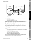
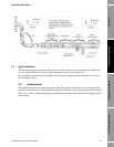
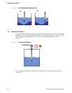
Figure 2-5 Pumped bypass
PT100
(optional)
Pump
10-30 l/min
Insulation
(required)
Optional drain line (½”)
either vented or
returned to process
Line or Base Viscosity: temperature not conditioned
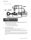
Horizontal Pipe line
Flowmeter
(optional)
1”-2” sample lines
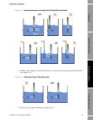
Always install the chamber with flow
in horizontal and flow out vertically
upwards.
Drain, to purge solids, is vertically
down and can be vented and/or
returned to line.
Side Wall Tapping
Side Wall Tapping
with Pitot Scoop
Meter in 2”
flow-through
chamber