


C-2
FACTORY MUTUAL (FM)
The FM entity parameters listed in Table 1 only apply to associated
apparatus with linear output.
.
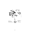
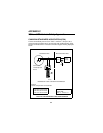
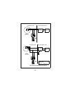
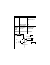
Before connecting the model 275 into the loop, determine the connected
inductance of the system by adding the L
i of the transmitter and cable.
The sum must be less than the L
a, as determined from Table 2, before the
275 can be connected into the loop.
If the connected inductance is greater than the value determined from the
table, a barrier with a lower I
sc must be chosen.
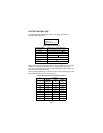
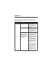
Table 1: FM Entity Parameters
Input Parameters ClassI,Div.1,GroupsA,B,C,D
Vmax =30Vdc VT or Voc of barrier must be < 30Vdc
Imax =300mAIT or Isc of barrier must be< 300 mA
C
i =0.07µFCA of barrier must be > 0.07 µF
L
i =0mHLA of barrier must be> 0 mH
Output Parameters
Voc =1.7Vdc N/A
I
sc =32mAN/A
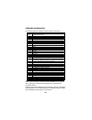
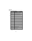
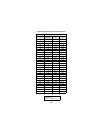
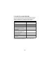
Table 2: Maximum Allowable Connected Inductance
Im La (mH)
(mA)
Groups
A&B
Group
C
Group
D
300 0.20 1.80 3.20
280 0.21 2.00 3.70
270 0.23 2.20 3.90
260 0.25 2.50 4.30
250 0.27 2.70 4.60
240 0.30 3.00 5.00
220 0.40 3.20 5.90
200 0.50 4.00 7.20
180 0.60 5.00 8.80
00275-0081
DWG No.
Rev. D. Sheet 1 of 2