


3-23
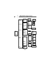
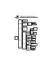
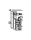
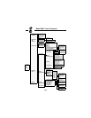
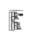
Model 3680 Density Transmitter
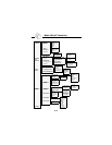
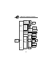
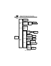
1 Process Variable
2 PV Percent Range
3PVOutput
4PVUnits
5Temp
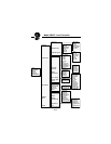
1Tag
2 RANGE & UNITS
3DATE&TIME
4 DAMPING
1 Last Reference
2 Counts
3 Reference Material
4NewReference
1PVUnits
2 Upper Range Value
3 Lower Range Value
4 Upper Sensor Limit
5 Lower Sensor Limit
6 DensityofCarrier
7 Density of Material
1PVDamp
2 ADAPTIVE DAMPING
1 Digital-to-Analog Trim
2ScaledD/ATrim
1 Manufacturer
2 Model
3 Poll Address
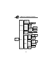
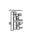
1DEVICE
SETUP
2PV
3 PV Output
4LRV
5URV
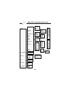
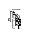
1 PROCESS
VARIABLES
2DIAGNOSTICS
AND SERVICE
3 BASIC SETUP
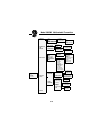
4DETAILED
SETUP
5REVIEW
1TestDevice
2 Loop Test
3 CALIBRATE
1 REFERENCE
2 Calibration Curve
3 PROCESS
SAMPLE
4 Density Offset
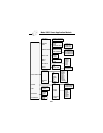
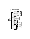
1 TEMPERATURE
COMPENSATION
2 OUTPUT TRIM
3 FIELD DEVICE
INFORMATION
1RTD
24to20mA
3 None
1 Temperature
Compensation
Status
2 Temperature Units
3COMPENSATION
PARAMETERS
4 SENSOR TYPE
1SourceType
2 Last Setup Location
3Sensors/n
4 UNIVERSAL
VARIABLES
5 Pipe Description
6 Process Description
7 Message
8Descriptor
9 Final Assembly Number
1 SoftwareRevision
1 Sample
2 Sample Duration
3NewSample
1Date
2 Time – Hours
3 Time – Minutes
1 Adaptive Damp Status
2 Adaptive Damp Value
3 Damping Threshold
1 Reference Temperature
2 Expansion Coefficient
3Rho1
4 Temperature 1
5Rho2
6 Temperature 2