


1-13
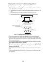
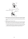
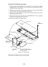
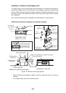
Control head modification procedure
1. Unfasten eight screws (M4X8) on the underside of the control head. Unplug
connectors P314, P312 and P317 from the control head. Separate the KB bot-
tom plate from the control head.
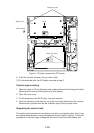
2. Unfasten the screw (M4) fixing the ground terminal and two screws (M4X8)
fixing the clamp. Remove the connection cable assy.
3. Unfasten two screws (M6X12) from the inside of the bottom plate of the control
head to dismount the handle.
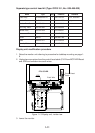
4. Replace the cable assy. with cable assy. UL2464SB2-0P/1P (10 m, supplied)
as below and reassemble the control head.
5. Paste warning label to the bottom plate.
KB BOTTOM
PLATE
P312 FX Connector
P314 XH3P
J312 (underside)
J314 (underside)
Lay cable in slot.
Screw
M4X8 (8 pcs.)
Pan-head Screw M4X8 (2 pcs.)
Be careful not to pinch cable between
KB clamp and spacer.
Spacer
KB Clamp
Earth Wire
Upset Screw
M6X12 (2 pcs.)
Handle
Replace with
cable assy. in
kit.
J317 (underside)
Warning label
Figure 1-15 Control head
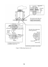
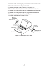
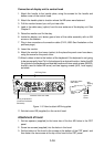
Connection of display unit to control head