


2-3
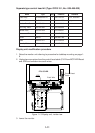
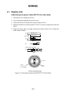
Cable fed from outside display unit
(B) Power clamp
(Aluminum)
(C) Signal clamp
(Aluminum)
(D) Rear clamp plate
(A) Rear clamp base
Bottom clamp front plate
(Installation materials)
(Display unit, right-hand side view)
M5x10 (2 pcs)
(Installation materials)
Back cable entrance
Shielding foam
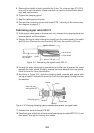
Figure 2-3 Clamp position outside display unit
• Place shielding foam between cables inside of display unit, and then attach
foam to chassis.
• Fill unused clamp holes with shielding foam.
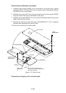
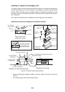
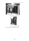
Cables fed from bottom of display unit (console mount)
Lead in cables through the cable clamp at the rear of the console and ground their
shields in the cable clamp. For signal cable, remove vinyl sheath where cable lies
in cable clamp. Fasten cables with cable ties.
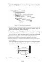
Close shutter and cover
with aluminum tape to
keep foreign objects out
of the display unit.
SIGNAL CABLE:
Remove the vinyl sheath here.
(1300 mm from display unit end
of cable remove sheath by 70 mm.)
Seventh hole
from the top
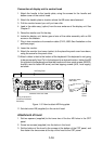
Close shutter door and cover
it with aluminum tape to keep
foreign objects out of the
display unit.
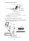
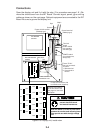
Gyrocompass
Power Cable
(For display unit)
Signal Cable
ARPA
Slave Display
NAV
Log
Performance
Monitor
Cable Arrangement in the Console (Top view)
Power Cable
(For PM)
Figure 2-4 Clamp position at bottom of display unit