


4-12
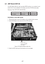
10.Fasten the front panel on the display pedestal.
11.Retract the stay to close the display unit.
12.Fasten the right arm cover.
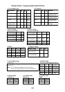
Separate type control head
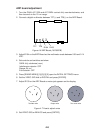
Necessary parts: RP-26-Z-2E (Code no. 008-491-400)
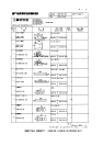
emaNepyTytQ.oNedoC
.yssAesaCdraC–1–
draoBPR8920P411046-784-800
BwercSdaeHnaPW0072C8x4M1544-188-000
BwercSdaeHnaPW0072C8x3M2404-188-000
AwercSdaeHnaPW0072C5x6.2M2379-008-000
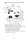
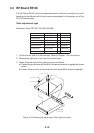
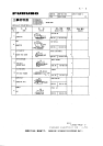
1. Lift the monitor. See Chapter 1 for instructions.
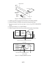
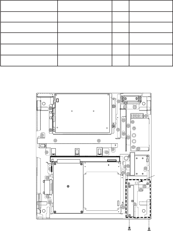
2. Fasten the mounting base with one M4 x 8 screw as below.
✂
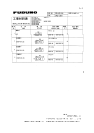
Fasten with
M4 x 8 screws.
Fasten with M3 x 8
screws (2 pcs.)
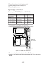
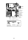
Figure 4-12 Display unit, inside view
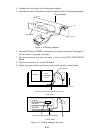
3. Fix the mounting base to front panel with two M3 x 8 screws.
4. Set the M-card case lid to the hole in the front panel and fix with two M2.6 x 5
screws.