


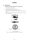
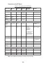
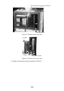
2-8
9. Remove the sheath of each conductor by 6 mm. Fix crimp-on lugs (FV1.25-4,
blue, ø4) to each conductor. Make sure each connection is secure both electri-
cally and mechanically.
10.Tighten the clamping gland.
11.Seal the cable gland with putty.
12.Connect the conductors to terminal board STB-1 referring to the interconnec-
tion diagram on page S-1.
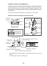
Fabricating signal cable S03-74
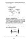
13.At the signal cable gland on the scanner unit, unfasten the clamping gland and
remove gasket and flat washers.
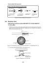
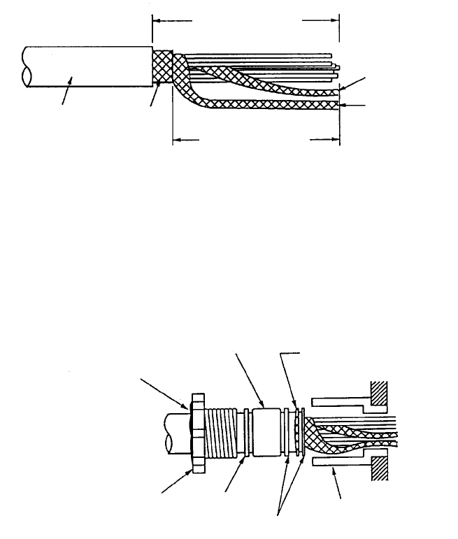
14.Shorten the signal cable making the length from the cable gland to the cable
end 500 mm. Remove the vinyl sheath by 550 mm; the armor by 540 mm.
Approx. 550 mm
Anti-corrosive
vinyl sheath
Armor
Approx. 540 mm
Inner shield
Outer shield
Figure 2-11 Fabricating the signal cable S03-74
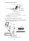
15.Unravel the outer shield with a screwdriver or similar tool to expose the cores
beneath the outer shield. Similarly, expose the cores beneath the inner shield.
Mark all cores for future identification.
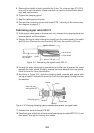
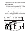
16.As shown in Figure 2-12, slide the clamping gland, washers and gasket onto
the signal cable. Fold back the armor by 5 mm, and then pass it through the two
flat washers.
Gasket
Armor
Clamping gland
Washer
Washer
Gland body
Seal with putty
after tightening.
Figure 2-12 Passing clamping gland, washers and gasket on signal cable
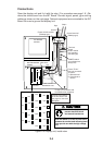
17.Unfasten the terminal board RTB-801.
18.Pass the signal cable behind the terminal board plate for cable MPYCY-12, and
then pass it through the locking wire saddle.