


2-11
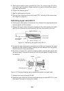
26.Check for miswiring, loose screws. Grease the fixing bolts for the cover, gas-
ket, and tap holes in the scanner chassis. Attach the cover.
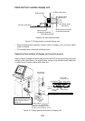
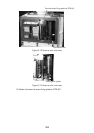
When the de-icer is installed
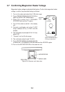
1) Before beginning any work on the scanner unit, turn off the breaker for the de-
icer line at the main switchboard to remove the power (100 VAC, 1ø) to the de-
icer. (Turning off the power to the display unit has no effect.)
2) The neck of the scanner unit becomes VERY HOT when the de-icer is working.
(The de-icer turns on when ambient temperature is below 0°C.)
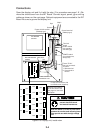
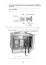
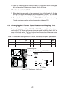
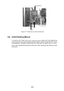
2.3 Changing AC Power Specification of Display Unit
To operate the display unit from 100 VAC or 220 VAC power, add or delete jumper
wires on the PTU Board and change the power fuses inside the display unit as
shown in the table below. The figure below shows the location of the power fuses
and the jumper wires on the PTU Board.
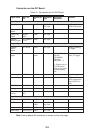
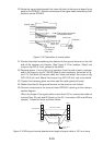
Table 2-2 Jumper wire setting on the PTU board, fuse rating and power specification
BCP.cepSrewoP
annetnA
mpr
1PJ2PJ3PJ4PJ19PJ29PJ
rewoP
sesuF
A5429P30CAV511/011/001mpr42SEYSEYSEYONONONA01
D5429P30CAV032/022mpr42ONONONSEYONONA5
✂
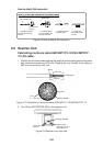
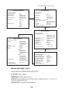
PTU Board
Fuse
Jumper wire to use:
JP1: 0.8 dia. gilded wire
JP2, JP3, JP4, JP91, JP92: type ERD-S2TCOV
03P9245
JP91
JP1
JP92
JP4
JP3
JP2
C11
C12
T1
T21
U92
JP92
Figure 2-17 Display unit, inside view