


1-14
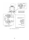
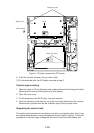
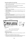
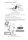
Connection of display unit to control head
1. Attach the handle to the handle plate, using the screws for the handle and
bottom cover of the control head.
2. Attach the handle plate to location where the KB arms were fastened.
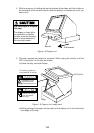
3. Pull the monitor toward you until you hear click.
4. Lead in the cable assy. (option) from the rear entrance of the display unit. See
Chapter 2.
5. Raise the monitor and fix the stay.
6. Inside the display unit, fasten ground wire of the cable assembly with an M4
screw on the chassis.
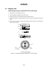
7. Plug in two connectors of connection cable (P412, J583: See illustration on the
previous page.)
8. Lower the monitor.
9. Attach the monitor front cover (option) to the place the panel cover have been,
using the screw for the panel cover.
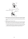
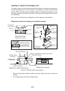
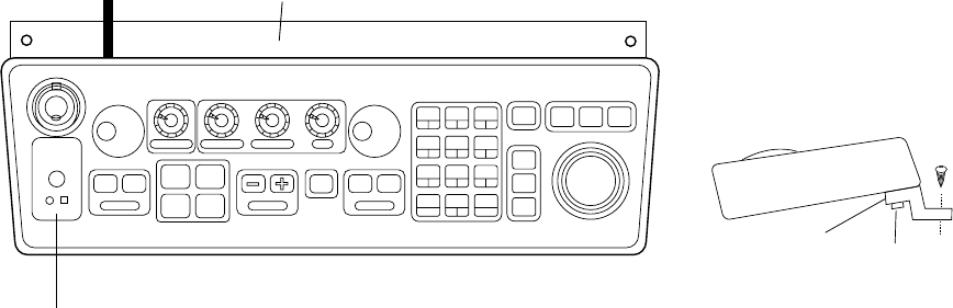
10.Attach rubber to feet to the bottom of the keyboard if the keyboard is not going
to be permanently fixed. To fix the keyboard to a desired location, fasten the KB
fixing plate to the keyboard and desired location with two upset screws (M5X25,
formerly used to fasten KB arms) and two tapping screws (φ6.5, local supply)
as below.
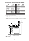
KB Fixing Plate
KB Fixing
Plate
CONTROL HEAD
SIDE VIEW
M5X25
Upset
Screw
φ6.5
Tapping
Screw
Tuning compartment
(Performance Monitor
SW inside)
CONTROL HEAD TOP VIEW
Figure 1-16 How to attach KB fixing plate
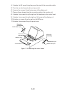
11.Set dust cover KB (supplied) on the control head.
Attachment of hood
1. Set two spacers (supplied) to the lower two of the four M5 holes in the CRT
panel.
2. Screw two screws (supplied) into the holes in the hood.
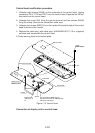
3. Set the bottom of the hood to the screws at the bottom of the CRT panel, and
then fasten the two screws at the top of the hood to the CRT panel.