


4-11
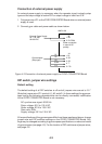
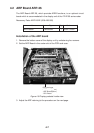
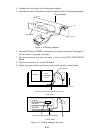
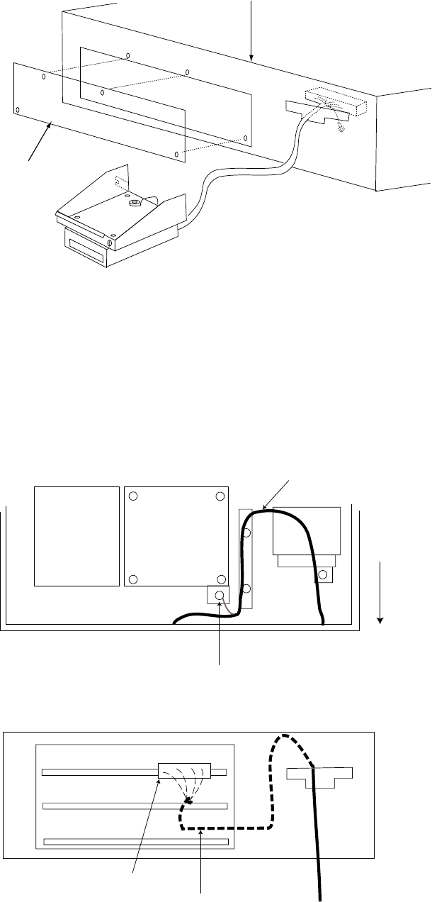
4. Unfasten the front panel from the display pedestal.
5. Pass the connector from the card case through the hole in the display pedestal.
Display pedestal
Front panel
Figure 4-10 Display pedestal
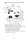
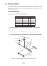
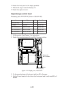
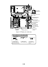
6. Set the RP Board (14P0298) in the top slot of the pcb card case. See page 4-7
for the location of the pcb card case.
7. Run the connector from the card case in front of the GYRO CONVERTER
Board.
8. Plug the connector in J1 on the RP Board.
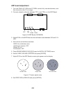
9. Fasten the ground wire from the connector at the location shown below.
INT Board
GYRO
CONVERTER
Board
FRONT
Fasten ground wire from connector to this screw.
RP connector
(TOP VIEW)
(FRONT VIEW)
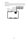
RP Board
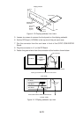
ARP Board
SPU Board
Route cable between ARP and SPU Boards.
J1
Figure 4-11 Display pedestal, top view