


2-2
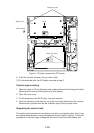
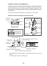
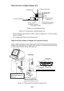
Leading in cables to the display unit
The cable clamp may be positioned inside the display unit (default arrangement),
outside the display unit or at the bottom of the display unit (when using console
mount). When the cable clamp is located outside or beneath the display unit, use
the bottom clamp front plate and bottom clamp rear plate (supplied with installa-
tion materials).
Also, use the shielding foam (supplied) to protect against noise radiation.
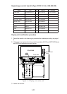
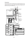
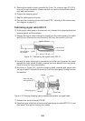
Cable fed from back of display unit (default method)
Panhead screw
M4X8
Hex bolt
M5X12 SUS
2 pcs
Hex bolt
M5X35 SUS
2 pcs
Hex bolt
M5X35 SUS
2 pcs
(A) Rear clamp
base
(B) Power clamp
(Aluminum)
(C) Signal clamp
(Aluminum)
(D) Rear clamp
plate
(B) Power clamp
(Aluminum)
(C) Signal cable
(Aluminum)
(D) Rear clamp plate
(A) Rear clamp base
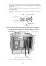
Cable position in clamp
(Display unit, rear view)
PWR
SCAN
Log
Keyboard
Navigation
Nav equipment
(Gyrocompass)
Slave display
External CRT
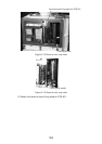
Rear cable entrance
Cable
Shielding foam
(Display unit, right-hand side view)
(Display unit, rear view)
(Construction of
cable clamp)
Make sure shielding foam contacts rear chassis.
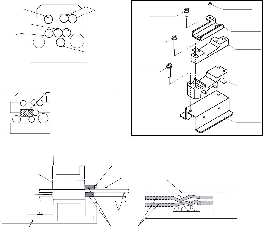
Nonslip rubber
If speed log and navigator
are not connected, paste
the nonslip rubber to the
clamp and secure cables.
Figure 2-2 Default cable clamp position
• Place shielding foam between cables, and then attach the foam to aluminum
clamps.
• Fill unused clamp holes with shielding foam.