


1-11
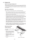
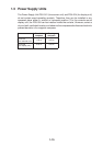
Separate type control head kit (Type: OP03-151, No.: 008-485-530)
emaNepyTytQ.oNedoCskrameR
.yssAelbaCP1/P02BS642LU1218-041-0002249S30,m01
rebbuRpilsnoN
teeF
5054-C-2401-A4689-008-000epat/w
tnorFrotinoM
revoC
1631-441-301043-362-001
etalPgnixiFBK1961-441-301049-362-001
etalPeldnaH2361-441-301040-862-001
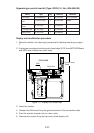
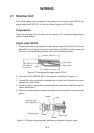
Display unit modification procedure
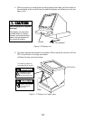
1. Raise the monitor unit referring to procedure for tabletop mounting on page 1-
7.
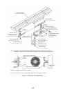
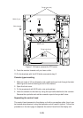
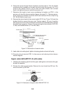
2. Unplug two connectors from the control head cable (P412 from MOTHER Board
and J583) and unfasten two earth wires.
MB 03P9251
INT
03P9252
J583
P412
J418
Earth Wire
PTU COVER
Control Head
Cable
Figure 1-11 Display unit, inside view
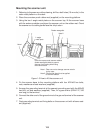
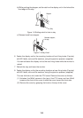
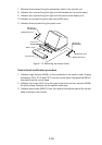
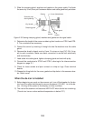
3. Lower the monitor.
4. Unfasten the M4 screw fixing the ground terminal of the connection cable.
5. Push the monitor forward until you hear a click.
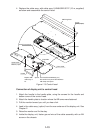
6. Unscrew four screws fixing the top cover of the display unit.