


2-8
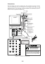
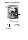
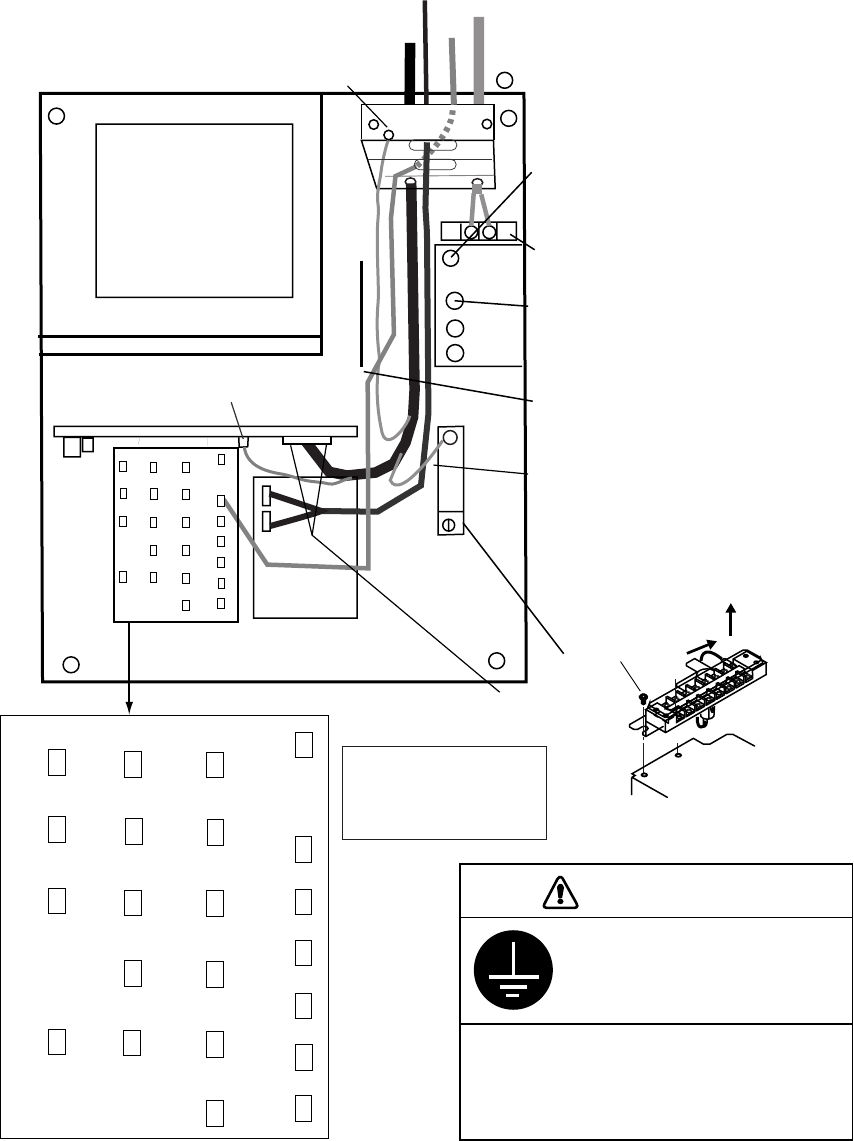
Connections
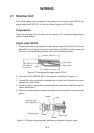
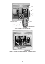
Open the display unit and fix it with the stay. (For procedure see page 1-6.) Re-
move the shield cover from the INT Board. Connect signal, power, gyro and log
cables as shown on the next page. Optional equipment are connected to the INT
Board. Be sure to ground the display unit.
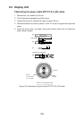
PTU BOARD
03P9245
INT BOARD
03P9252
GYRO CONVERTER
BOARD 64P1106
MOTHER BOARD
03P9251
J5
J4
Fasten shield here.
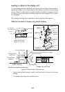
(Tabletop type)
Terminal
board
Ship’s
mains
Scanner
Unit
Gyro
Log
POWER switch
(for maintenance,
always ON)
J448
DJ1
J446
J467
J469
J448
J445
J449
J465
J455
J466
J454
J450
J462
J456
J453
J451
J458
J457
J452
J442
J443
J444
J463
Connect coax
cable here.
1
Fasten TX-HV
line to #1 terminal.
To fasten;
1. Slide terminal.
2. Lift terminal to
remove.
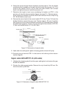
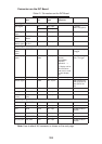
Location of connectors
on the INT Board. See
next page for connector
description.
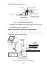
Fix the DJ1 connector with
two M3x8 screws (supplied).
Signal cable should
touch edge of
partition board.
Ground terminal
(Tabletop type)
Fasten shields
here together.
(Console type)
✔
✚
✖
✗
✘
✕
✛
✙
M4X8 (2 pcs.)
1
2
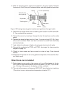
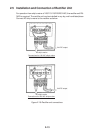
Figure 2-12 Display unit, inside view
Ground the equipment to
prevent electrical shock
and mutual interference.
CAUTION
Bind the cables so as not to pinch them
between the monitor and mounting base.
Take special care with the high voltage
line.