


iii
TABLE OF CONTENTS
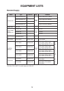
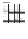
EQUIPMENT LISTS ............................................................................ iv
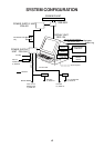
SYSTEM CONFIGURATION ............................................................... vi
MOUNTING
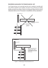
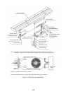
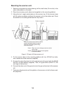
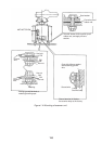
1.1 Scanner Unit ............................................................................................................. 1-1
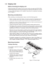
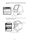
1.2 Display Unit ............................................................................................................... 1-7
1.3 Power Supply Units ................................................................................................. 1-15
WIRING
2.1 Scanner Unit ............................................................................................................. 2-1
2.2 Display Unit ............................................................................................................... 2-5
2.3 Changing AC Power Specification of Display Unit .................................................. 2-10
2.4 Power Supply Units ..................................................................................................2-11
2.5 Installation and Connection of Rectifier Unit ........................................................... 2-13
INITIALIZATION AND ADJUSTMENT
3.1 Tuning Initialization.................................................................................................... 3-1
3.2 Accessing Menus for Initialization and Adjustment ................................................... 3-1
3.3 Adjusting Video Signal Level..................................................................................... 3-1
3.4 Heading Alignment .................................................................................................... 3-2
3.5 Adjusting Sweep Timing ............................................................................................ 3-3
3.6 Suppressing Main Bang ............................................................................................ 3-3
3.7 Confirming Magnetron Heater Voltage ...................................................................... 3-4
3.8 Initial Setting Menus .................................................................................................. 3-6
INSTALLATION OF OPTIONAL EQUIPMENT
4.1 Gyro Converter GC-8 ................................................................................................ 4-1
4.2 ARP Board ARP-26 ................................................................................................... 4-7
4.3 RP Board RP-26...................................................................................................... 4-10
4.4 Performance Monitor PM-30 ................................................................................... 4-14
4.5 Alarm Kit.................................................................................................................. 4-15
PACKING LISTS........................................................................................................ A-1
OUTLINE DRAWINGS............................................................................................D-1
INTERCONNECTION DIAGRAM ...................................................................... S-1
SCHEMATIC DIAGRAMS ..................................................................................... S-2