


4-2
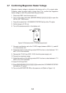
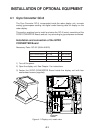
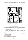
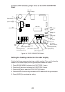
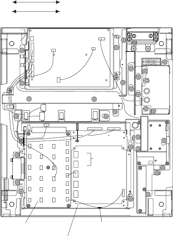
4) Connect the GYRO CONVERTER Board to the INT Board (cables supplied
with GC-8) as shown below.
INT Board GYRO CONVERTER Board
J446 (4P) J7 (5P)
J465 (6P) J1 (14P)
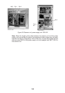
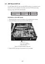
INT BOARD
03P9252
GYRO CONVERTER
BOARD 64P1106
J1
J5
J4
To gyro
J7
Fix cable to chassis
with cable tie.
J446
Figure 4-2 Display unit, inside view
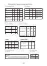
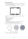
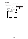
5) Confirm gyrocompass specifications and set up the DIP switches and jumper
wires on the GYRO CONVERTER Board according to gyrocompass connected:
• Setting jumper wires and DIP switches by gyrocompass
specifications: page 4-3
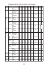
• Setting jumper wires and DIP switches by make and
model of gyrocompass: page 4-5
• Location of jumper wires and DIP switches: page 4-6
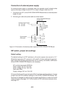
6) Solder the gyrocompass cable to the VH connector assemblies (supplied).
7) Attach instruction label (supplied) to the shield cover for the INT and GYRO
CONVERTER boards.
8) Close the display unit.
9) Turn the power off and on to reset the CPU.