


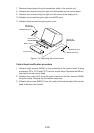
1-12
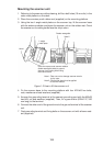
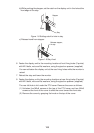
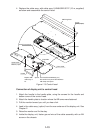
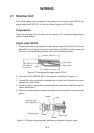
7. Remove three clamps fixing the connection cable in the monitor unit.
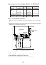
8. Unfasten four screws fixing the right and left brackets on the control head.
9. Unfasten four screws fixing the right and left covers of the display unit.
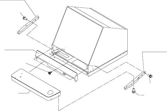
10.Unfasten six screws fixing the right and left KB arms.
11.Unfasten three screws fixing the panel cover.
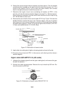
KB arm (L)
03-144-1341
M5x25 SUS 3 pcs.
Panel cover
03-144-1345
M4x10, 3 pcs.
Control head
M5x25 SUS 4 pcs.
M5x25 SUS 3 pcs.
KB arm (R)
03-144-1342
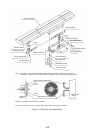
Figure 1-12 Detaching the control head
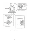
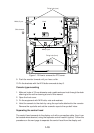
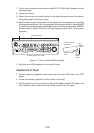
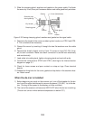
Control head modification procedure
1. Unfasten eight screws (M4X8) on the underside of the control head. Unplug
connectors P314, P312 and P317 from the control head. Separate the KB bot-
tom plate from the control head.
2. Unfasten the screw (M4) fixing the ground terminal and two screws (M4X8)
fixing the clamp. Remove the connection cable assy.
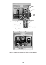
3. Unfasten two screws (M6X12) from the inside of the bottom plate of the control
head to dismount the handle.